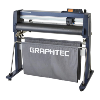
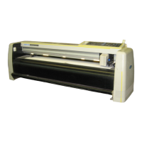
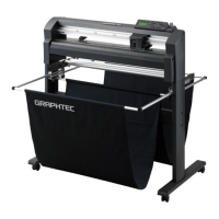
Do you have a question about the GRAPHTEC FC9000-75 and is the answer not in the manual?
Details the main technical specifications of the FC9000 series cutting plotters.
Provides the physical dimensions of the FC9000 series plotters, including stand.
Lists optional accessories and consumable supply parts for the FC9000 series.
Instructions to verify all standard accessories are present in the box.
Step-by-step guide for assembling the plotter stand and media basket.
Identifies and describes the main external and internal parts of the plotter.
Procedure for correctly attaching cutter pens or plot pens to the tool holder.
Detailed steps for safely replacing the cross-cutter blade.
Explains the function of each key and indicator lamp on the plotter's control panel.
Guide to interpreting the information displayed on the plotter's LCD screen.
Lists the necessary tools required for maintenance and adjustments.
Specifies points requiring lubrication and the type of grease or glue.
Procedures for disassembling and reassembling the external covers and panels.
Step-by-step guides for disassembling and replacing internal components.
Instructions for adjusting the tension of the Y and X drive belts.
Guidance on verifying correct cable connections after reassembly.
Table indicating which items need readjustment after component replacement.
Provides flowcharts for adjustment procedures after component replacement.
Details the DIP switch configurations for different models and modes.
Instructions on how to access the plotter's adjustment menu.
Procedures for adjusting pen force, either from recorded values or measured force.
Guides on setting distance and perpendicularity accuracy from recorded or measured values.
Steps to adjust the sensitivity of the registration mark sensor.
Procedure to adjust the offset position of the registration mark sensor.
Steps to adjust the X media sensor position and registration mark sensor position.
Procedure to set the 2nd pen exchange position for dual pen systems.
Adjusts the spacing between the first and second tools in dual pen setups.
Diagnoses and solutions for the plotter not powering on or initializing.
Troubleshooting steps for issues related to media loading and positioning.
Addresses common problems encountered during cutting operations.
Troubleshooting for issues with print and cut registration mark detection.
Solutions for problems related to plotter detection by Windows via USB.
Lists and explains various error codes and their causes/solutions.
Details on entering service mode for diagnostics and testing.
Lists part numbers for the plotter's exterior covers and panels.
Part numbers for the control panel assembly, including keys and LCD.
Part numbers for the pen block assembly and its components.
Lists main electrical components like main board, power supply, and motors.
Part numbers for the Y-axis drive system components.
Part numbers for components related to the Y-axis slider.
Part numbers for the X-axis drive system components.
Part numbers for the plotter stand and media basket assembly.
Procedure for removing the main printed circuit board for WEEE.
Steps to remove the control panel board and LCD for WEEE compliance.
Procedure for removing the Y relay board for WEEE compliance.
Steps to remove the switching power supply unit for WEEE compliance.
| Model | FC9000-75 |
|---|---|
| Maximum Cutting Width | 750 mm |
| Maximum Media Width | 800 mm |
| Maximum Cutting Speed | 1000 mm/s |
| Mechanical Resolution | 0.025 mm |
| Repeatability | ±0.1 mm |
| Number of Tool Mounts | 1 |
| Media Hold-Down Method | Vacuum |
| Type | Plotter |
| Connectivity | USB, Serial, Ethernet |
| Command Sets | HP-GL, GP-GL |
| Power Supply | AC100 to 240 V, 50/60 Hz |
| Operating Environment | 10 - 35 °C, 35 - 80 % RH |
| Pen Force | 30-500 gf |
| Cutting Force | 0.49 to 58.8 N (5 to 600 gf), 48 steps |
| Programmable Resolution | 0.025 mm |


