FC9000-UM-251-9370 8-23
8 Electrical Adjustment
8.12 Adjusting the friction
ThisadjustmentwillsetthefrictioncoefcientfortheXandYmotors.
Perform this procedure if adjustment values could not copy from the SUB-NVRAM when replacing the main
board.
When the X or Y motor was replaced, perform this adjustment.
Required jigs
•
PreparethefollowingsizeofCuttinglm.
FC9000-75 and 100: (Length) 1200 mm x (Width) 762 mm (30 inch)
FC9000-140 and 160: (Length) 1200 mm x (Width) 1372 mm (54 inch)
Ifyoudon'thaveabovewidthofcuttinglm,prepareatleast30inchwidercuttinglm.
Andtheloadablewidestcuttinglmisbetterforthisadjustment.
Preparation
• Set the left and right push rollers pressure to high (Strong).
• Loadthecuttinglmaslengthoffrontandreartobesamelength.
• Movethepenblocktothecenterofcuttinglmwidth.
How to adjust the friction
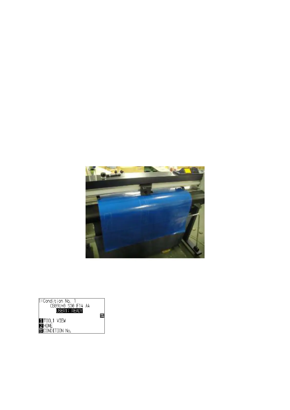
(1) Loadthecuttinglmtotheplotter.
(2) Turn on the power while pressing the SLOW and the ENTER keys.
(3) The plotter displays the following menu.