Do you have a question about the GRAPHTEC FC9000 Series and is the answer not in the manual?
Describes guidelines and important notes for using the user manual effectively.
Lists all registered trademarks and company names mentioned in the manual.
States the copyright ownership of the user manual.
Advises users to read safety instructions and precautions before operating the plotter.
Details safe handling procedures for cutter blades to prevent injury.
Provides instructions for safely handling cutter plungers and their blades.
A caution regarding touching the pen tip after mounting plungers.
Highlights the importance of observing caution labels located on the machine.
Important notes regarding the proper use and compatibility of the plotter stand.
Important notes regarding the proper use and compatibility of the plotter basket.
Advice and precautions for using media that is curled.
Advises users to secure adequate space for plotter operation and ventilation.
Details power cable specifications for 100-120V systems.
Details power cable specifications for 200-240V systems.
Lists all standard accessories included with the plotter package.
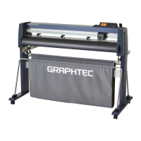
Identifies and labels all major parts of the plotter from the front view.
Step-by-step instructions for assembling the plotter unit.
Instructions on how to connect the plotter to a computer via various interfaces.
Details on cutter plunger types, nomenclature, and structure.
Procedure for mounting cutting tools and pens into the tool holder.
Step-by-step guide for loading both roll and sheet media correctly.
Instructions on how to align push rollers for proper media handling.
Explanation of the initial setup screens for language and unit settings.
Steps for safely connecting the plotter to a power source.
Explanation of the function of each button and indicator on the control panel.
Configuration options for how media is fed into the plotter.
Procedure for setting the pre-feed function to prevent media slippage.
Guide to selecting and configuring tool conditions like offset, speed, and force.
Performing test cuts to verify and optimize cutting parameters.
How to view the available cutting area dimensions on the plotter.
Function to manually adjust the vertical position of the tool (pen or cutter).
Manual movement controls for the tool carriage and media.
Procedure to define the starting point for cutting operations.
How to rotate the coordinate axes to change the cutting direction.
Instructions on how to pause, resume, or quit a cutting operation.
Adjusts cutting parameters like area, width, and page length.
Functionality for duplicating cut designs multiple times.
Feature to divide media into sections for sequential cutting.
Setting the force applied during cross-cutting operations.
Allows saving and switching between two sets of user preferences.
Introduction to the ARMS system and its capabilities.
Detailed procedures for configuring and adjusting the ARMS system.
Overview of manual adjustments for tool and media positioning.
Detailed steps for performing manual position adjustments.
Techniques for achieving sharp corners on thick media using tangential mode.
Adjusting step pass settings for smoother cutting of curves.
Adjusting the blade's angle to improve cutting quality.
Correcting deviations in cut or plotted line lengths.
Configuring perforated cut lines for easier media separation.
Adjusting the initial position of the blade for optimal contact.
Adjusting the force used for initial blade positioning.
Correcting misalignment between different tools or pens.
Procedure for manually or automatically cross-cutting roll media.
Optimizing the order of cutting operations to reduce processing time.
Enabling automatic pre-feed when cutting data is received from the computer.
Enabling automatic pre-feed when loading new media.
Adjusting the speed of the media during pre-feed operations.
Configuring the speed at which the tool moves when raised.
Determining how the tool moves when raised between operations.
Adjusting the vertical height of the tool when it is in the raised position.
Configuring the plotter's connection interfaces (USB, LAN, RS-232C).
Procedure to erase all output data stored in the plotter's buffer.
Detailed settings for configuring the network (LAN) interface.
Steps and settings required for connecting via an RS-232C interface.
Settings that affect how menus are displayed on the control panel.
Configuration options for media and push roller sensors.
Settings related to the plotter's operational environment.
Managing command types (GP-GL, HP-GL, AUTO) sent from the computer.
Specific settings for controlling the plotter using GP-GL commands.
Specific settings for controlling the plotter using HP-GL commands.
Choosing the target device for data output (USB drive, server).
Procedure for linking and transferring data using a USB memory device.
Using barcodes to identify and output cutting data.
Enabling automatic scanning of start marks for data linking.
Setting the time limit for data link communication before cancellation.
Detecting and compensating for media skew during continuous operation.
Enabling and configuring the Apparel mode for specialized cutting.
Introduction to axis adjustment techniques using alignment marks.
Procedure for adjusting the plotter's coordinate axes for accuracy.
Setting the 'F' command to enable or disable Cross Cut functionality.
Performing a demo cut to check plotter operation.
Configuring timeout settings for data input to the interface.
Setting separator commands for GP-GL and HP-GL to control cross cuts.
Procedure for outputting data from USB memory without computer connection.
Performing test cuts to verify and optimize cutting parameters.
Configuring parameters for cross-cutting operations.
Adjusting the rear margin for cross-cut placement.
Setting the number of pre-feeds to prevent media deviations.
Setting the time for media acclimation before cutting.
General procedures for creating and printing designs with registration marks.
Using barcodes for data linking and identifying cutting jobs.
Using barcodes for automated, continuous cutting of roll media.
Routine cleaning and care procedures for the plotter.
Step-by-step guide for safely replacing the cutter blade.
Procedure for cleaning dust and debris from the cutter pen.
Instructions for exchanging a worn cutter plunger.
Configuring alerts for when the cutter blade needs replacement.
Procedure for replacing the cross cut unit.
General guide to identifying and resolving common plotter issues.
How to print the current configuration settings of the plotter.
Procedure for generating test patterns to check plotter operation.
Steps to create custom cutting profiles for testing.
Verifying the transmission and accuracy of cutting data.
Running built-in diagnostic tests to check plotter hardware.
Function for creating perforated outlines on media using a pouncing tool.
Configuration for using and switching between two different tools or pens.
Step-by-step instructions for mounting the pouncing tool into the holder.
Important safety and usage notes for the take-up unit.
Identification of parts of the take-up unit from front and rear views.
Steps for preparing the plotter and media for take-up operation.
Guidance on resolving common issues with the take-up unit.
Supplementary information including specifications for the take-up unit.
Procedure for mounting the stock shaft into the media stocker.
Steps to enable and configure the take-up function.
Technical specifications for the take-up unit, including length, width, and weight.
Key technical specifications for all FC9000 models.
List of available optional accessories and consumable supplies.
Diagrams and measurements of the plotter's physical size.
Visual representation of the plotter's menu structure.
Default initial values for various plotter settings.
List of consumable items for the plotter.
List of optional accessories available for the plotter.
| Repeatability | ±0.1 mm |
|---|---|
| Model | FC9000-100, FC9000-160 |
| Max Cutting Width | 1626 mm (64 in) |
| Maximum Cutting Speed | 1485 mm/s (58.5 ips) |
| Cutting Force | 50-500 gf |
| Media Width | Up to 1370 mm (54") |
| Connectivity | USB, Ethernet |
| Display | LCD |
| Software Compatibility | Graphtec Pro Studio, Graphtec Studio, Cutting Master 4 |
| Media Type | Reflective film |
| Mechanical Resolution | 0.005 mm |
| Programmable Resolution | 0.025 mm |
| Command Sets | GP-GL, HP-GL |
| Power Supply | 100-240 VAC, 50/60 Hz |
| Media Thickness | 0.1 to 1.0 mm |
| Compatible Media | Card stock |


