Broadlinx
170 Planning and Installation Manual
Checking Switcher Signal Status
1. Connect to the router following the procedure described on
page 166.
2. Click on the graphic of the router front panel.
3. Select “Signals.”
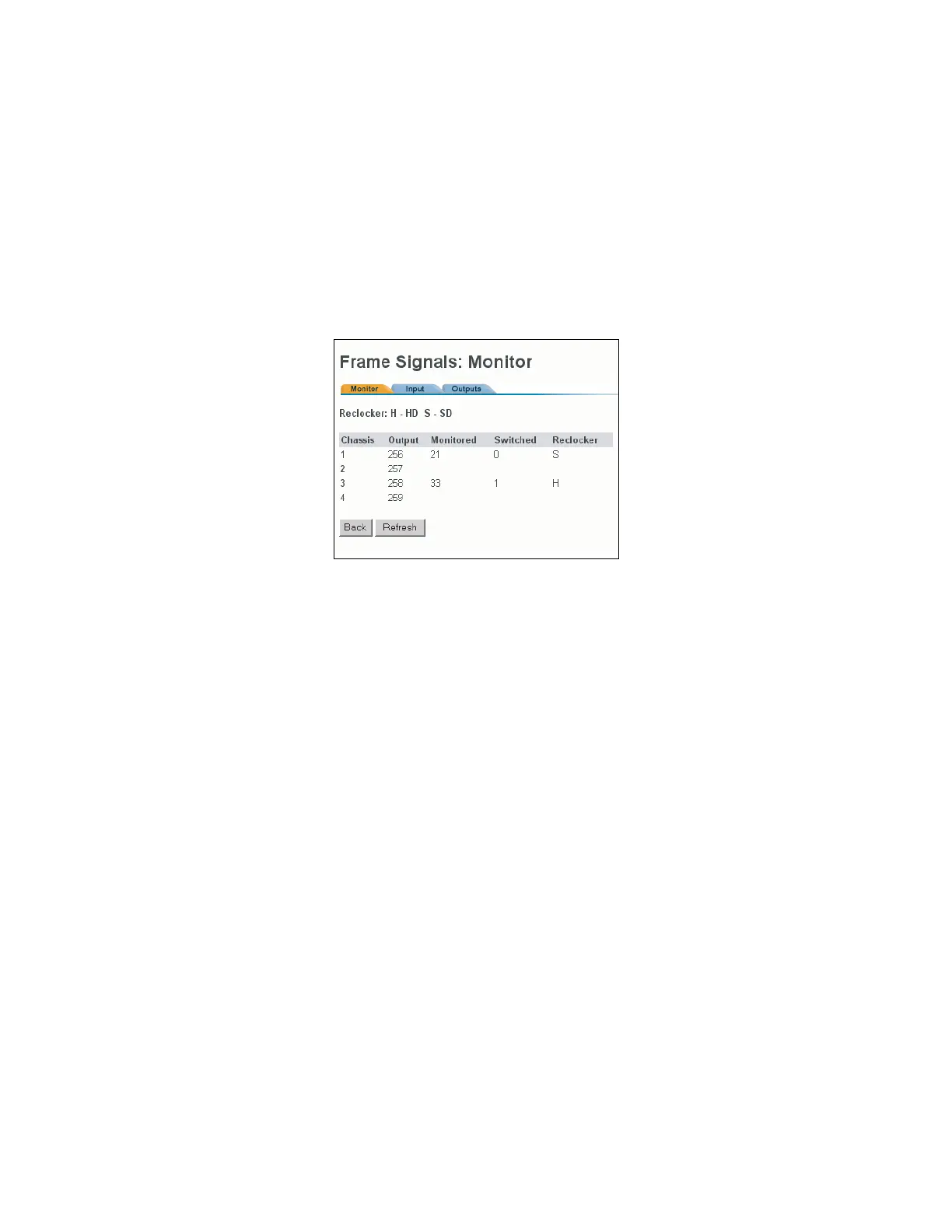
A menu similar to Figure 98 will appear.
Figure 98. Monitor Window (DV-33128 and DV-33256).
The Monitor tab displays the following:
• “Chassis” - this column lists the monitor output ports labelled
“1” through “4” on the back of the chassis.
• “Output”- numbers that are entered in the control system (e.g.,
Jupiter) to identify the Trinix monitor outputs. In this example,
which shows a 256 x 256 router, the four monitor output
numbers are 256, 257, 258, and 259 (in the Jupiter environment
these are referred to as “physical” output numbers). These
numbers correspond to monitor output ports labelled 1 through
4 on the rear of the chassis (as shown on page 139).
• “Monitored” - the number of the output that is being monitored
by the control system. In this example, output 21 is being sent to
monitor output port 2.
• “Switched” - the number of the input that is being switched to
this monitor output.
• “Reclocker” (DV-33128 and DV-33256) - “H” = monitor output
board is locked to (and is reclocking) an HD signal. “S” =
monitor output board is not reclocking this signal (because the
signal is either SD or Force Bypass mode is selected). For more
information about output monitor reclocking see page 142.
 Loading...