4-002 Description of the Individual Assembly Groups
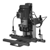
Machine frame of the Ecopress-Pneumatic Illustration 4-002-03
1 Right frame plate
2 Outflow device for condensation water
3 Pneumatic feed line
4 Regulating knob for pneumatic adjustment. Lift the knob to adjust. Turn clockwise to
increase the pressure. After the adjustment, press the regulating knob down on 5.5 - 6 bar.
5 Compressed air gauge
6 Control panel
7 Upper frame plate
8 Upper cylinder connection motor support
9 Lower cylinder connection motor support
10 Pneumatic cylinder
11 Electric motor
12 Control cam, changes from the feed speed to the operating speed
13 Start button for drilling and insertion cycle
14 Alternative switch for pneumatic hold down device - Accessory
15 Insertion arm
Machine frame of the Ecopress-Manual Illustration 4-002-04
1 Right frame plate
2 Electrical box
3 Limit switch, switches the electric motor on for the drilling cycle
4 Control cam is activate by the limit switch Pos. 3 ( the limit switch first activates the
control cam with drilling and in no case in the upper position of the Ecopress-Manual).
5 Hand lever for drilling and insertion
6 Electric motor
7 Insertion arm
8 Safety depth stop to prevent drilling into the machine table