4-004 Description of the Operating Features
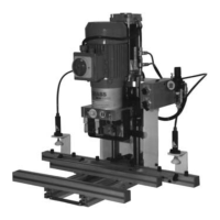
Ecopress-Pneumatic llustration 4-004-01
1 Start button for the stroke motion
As long as the start button is activated, the bore head moves downward until the
boring depth stop (position 4, illustration 4-002-02) sets on the workpiece,that is, until the
pneumatic cylinder has completed the stroke motion.
2 Selector switch for pneumatic hold down clamps is an accessory.
left position is for loose workpiece
right position is for tightened workpiece
3 Insertion dies are placed in the insertion arm.
4The main switch is installed in the terminal box of the electric motor.
Caution: This switch turns off only the electric motor, not the control system.
Ecopress-Manual Illustration 4-004-02
1 Hand lever is for the downward movement of the drill gearbox.
2 Insertion dies are placed in the insertion arm.
3The main switch is installed in the terminal box of the electric motor.
Caution: This switch turns off only the electric motor, not the control system.
4-005 Ecopress Machine’s Function
Ecopress-Pneumatic
By pressing the start button (position 1, illustration 4-004-01), the pneumatic valve (2) (illustration 4-006-01) is
activated and the pneumatic cylinder executes the upward motion of the boring head. The exhaust air of the cylinder
escapes through the pneumatic roller valve (3) (illustration 4-006-01) which is activated by the switch cam (12)
(illustration 4-002-03).
As soon as the switch cam releases the pneumatic roller valve, this valve closes. Now the exhaust air of this cylinder
has to escape through the one-way restrictor valve (6) (illustration 4-006-01).
Consequently, the exhaust air also flows through the one-way restrictor valve (4) (illustration 4-006-01) and activates
the P-E-transformer (5) (illustration 4-006-01), which turns on the power circuit protection K1 (illustration 4-007-01).
Thus, the motor operates.
After the escape of all the exhaust air from the cylinder, the air from the P-E transformer (5) (illustration 4-006-01) also
escapes through the one-way restrictor valve (4) (illustration 4-006-01), and the motor shuts off.
When the start button is released, the boring head returns to the uppermost position. The exhaust air of the upper
cylinder chamber is used to blow the wood shavings out of the bore hole.
Caution: The more the one-way restrictor valve is closed, the longer the motor will run after reaching the boring
depth; respectively, after the release of the start button.
Caution: The switch cam has to activate the pneumatic valve in the uppermost position. The switch cam has to be
installed high enough, so that the motor will not also run during the insertion.
Ecopress-Manual
All movements are manually operated on the Ecopress-Manual.
When the hand lever is pushed down, the boring head will also move down. The cam switch (1) (illustration 7-305-01)
is tightly connected to the boring head, which activates the roller limit switch (2) (illustration 7-305-01). As soon as the
roller limit switch is activated, the control system turns on the electric motor.
Caution: The cam switch must not activate the roller limit switch in the uppermost position. The cam switch must be
installed high enough so that the motor does not run during the insertion.
25
4. Machine-Parts Description