4-007 Electric Wiring Diagram Illustration 4-007-01
Pos. Type Bezeichnung Funktion
J1 HORNF 5 x 1.5 mm
2
Cable Lead cable
K1 Lovato B9 380V/50Hz Power protection Switches the electric motor on
F1 Lovato RC22 2-3.3A Thermal excess current Protects the motor from
release overloading
F2 SAKS 6 KrG Fuse terminal Safety for control circuit
DEF 63 1
1
/4” x
1
/4” Fuse link
Q1 ............................. Main switch built directly on Main switch
electric motor
S1 Festo P-E-1/8” P-E-transformer Switches on power circuit
protection
S2 Omron D4MC-2020 Roller limit switch Switches on power circuit
protection
S3 ........................... Electric volume flow monitor Motor runs only when dust
collection system is switched on
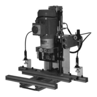
M1 ........................... Electric motor Motor drive for drill gearbox
S1 available only with Ecopress-Pneumatic
S2 available only with Ecopress-Manual
S3, if required is availble from Grass as an accessory. In position S3, a direct connection of x1 to x2 is available
in the electric switch box. Should an electric volume flow monitor be added, it should be connected to x1 and x2.
29
4. Machine-Parts Description