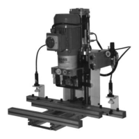
8-001 Incorrect Drilling Distance — Adjustment of Scale Illustration 8-001-01
- Turn off the main switch
- Take off the gearbox cover.
- Remove all existing drill bits, including fastening screws, from the gearbox.
- Fasten a drill bit on the hinge cup drill-spindle
- Gearbox placement, see illustration 7-401-01.
- Hang in gearbox cover.
- Turn on the main switch.
- Place the test workpiece on the machine table and press against the stops on the fence.
- Measure the boring distance ”a” on the test workpiece and compare it with the set value on the
scale. In case both values are not identical:
- Loosen both screws (1) with a 5 mm Allen wrench and set the scale to the measured value. Tighten both screws.
- Complete another test drilling until both values match.
8-002 Boring Head’s Operating Speed Cannot Be Adjusted only with Ecopress-Pneumatic
If the operating speed cannot be adjusted (according to chapter 7-303), a technician or specialist must be consulted.
”Pneumatic Wiring Diagram”, chapter 4-006.
8-003 Motor Does Not Run
- Turn off the main switch. Check if the drill gearbox turns manually on a gearbox spindle. The ventilation wheel
must turn thereby. (If this is not the case, then the gearbox can sustain mechanical damages.)
- Turn on the main switch on the motor.
- Press the blue button on the cover of the electric switch box; the thermal overload relay has kicked in.
- Check to see if the machine is plugged in.
- The Ecopress-Manual: Does the switch cam activate the limit switch during the drilling cycle? Illustration 7-305-01.
- The Ecopress-Pneumatic: Does the switch cam release the roller of the pneumatic valve during the drilling cycle?
Illustration 7-305-01.
- Check the fuses in the in-house electric distributing panel.
- If points are unsuccessful, then consult a specialist or technician. See wiring diagram in Chapter 4-007.
67
8. Trouble Shooting and Problem Solving