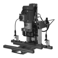
4-006 Pneumatic Wiring Diagram of the Ecopress-Pneumatic Illustration 4-006-01
Pos. Type Description Function
1 Hörbiger MKS-08 H Filter-pressure reducer 1/4” Pressure regulator and filter unit
including pneumatic air gauge
2 Festo SV5-M5B 5/2-type valve M5 Start valve for boring and
Festo T-22-S press button insertion cycle
3 Bosch 0 820 402 015 2/2-type valve 1/8” Reversing valve from feeding to
(Hörbiger K9 321RF-1/8”) 3/2-type valve-1/8” operating speed
4 Camozzi RFU-482 One-way restrictor valve 1/8” Motor after-running time
5 Festo P-E-1/8” P-E-transformer 1/8” Switches on motor protection
6 Hörbiger DRV-1/8” One-way restrictor valve 1/8” Adjusts the operating speed
7 Camozzi HGL Controllable back pressure Safety valve
valve 1/4”
8 Cam. 26N 2A 080 A 0125 Double action cylinder Thruster cylinder
both sided final position absorber
9 Festo SV3-M5B 3/2-type-valve M5 Selector switch for pneumatic
Festo N-22-S Selector switch hold down device
10 Festo EFK-10-40 P Single-acting cylinder Pneumatic hold down device
Position 9 and Position 10 are available as accessories.
27
4. Machine-Parts Description