13
4 Unit Control
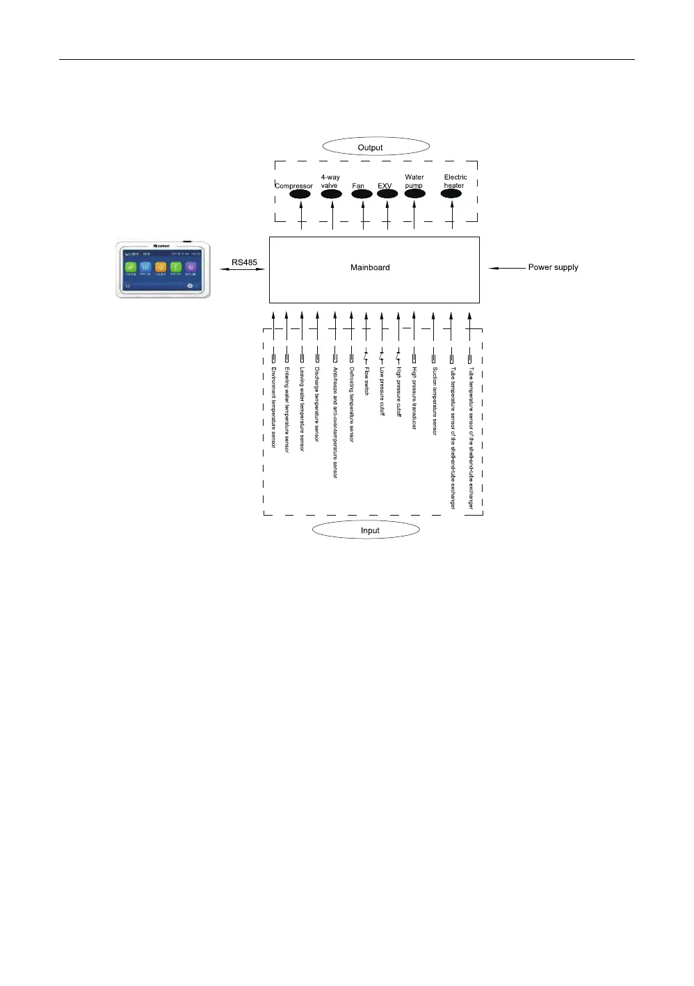
4.1 Schematic Diagram
Description:
(1)A water flow cutout is used to judge the water flow rate. When the flow rate is too low, it
will trip off, and the control board will send this signal to the display and the water pump.
Then, the display will tell there is an error, the water pump will stop and the unit will stop or
will not start.
(2)A high/low pressure cutout is used to judge the system pressure. When the system pres-
sure is too high/low, it will trip off, and the control board will send this signal to the display.
Then, the display will tell there is an error and the unit will stop or will not start
(3)An ambient temperature sensor is used to detect the temperature of the environment
where the unit is which will determine whether to start or stop the fan and determine the
steps of the electrostatic expansion valve when initializing. When this sensor fails, the con-
trol board will detect and send this signal to the display. Then, the display will tell there is
an error and the unit will stop or will not start.
(4)A discharge temperature sensor is used to detect the discharge temperature. When the
sensed temperature is too high or this sensor fails, the control board will detect and send
this signal to the display. Then, the display will tell there is an error and the unit will stop or
will not start.
A Series Modular-type Air-cooled (Heat Pump) Chiller
 Loading...