EasyManua.ls Logo

Grizzly G0704 - User Manual

Grizzly G0704
61 pages
Print Icon
To Next Page IconTo Next Page
Loading...
COPYRIGHT © JUNE, 2014 BY GRIZZLY INDUSTRIAL, INC.
WARNING: NO PORTION OF THIS MANUAL MAY BE REPRODUCED IN ANY SHAPE
OR FORM WITHOUT THE WRITTEN APPROVAL OF GRIZZLY INDUSTRIAL, INC.
#TS16629 PRINTED IN CHINA
The following changes were made to this machine since the owner's manual was printed:
Motor assembly changed—motor shaft is now 14mm OD.
Motor gear and ring changed to 14mm ID.
Added stand assembly parts breakdown and list.
Note: On the parts list, the new parts are designated with a “V2” or “V3”.
Aside from this information, all other content in the owner's manual applies and MUST be read and under-
stood for your own safety. IMPORTANT: Keep this update with the owner's manual for future reference.
For questions or help, contact our Tech Support at (570) 546-9663 or techsupport@grizzly.com.
READ THIS FIRST
For questions or help with this product contact Tech Support at (570) 546-9663 or techsupport@grizzly.com
Model G0704
***IMPORTANT UPDATE***
For Machines Mfd. Since April, 2013
& Owner's Manual Revised February, 2013
229V2
230V2
231
221V3
221-1V2
221-2V2
REF PART # DESCRIPTION
221V3 P0704221V3 MOTOR 1HP 110V (14MM SHAFT) V3.04.13
221-1V2 P0704221-1V2 CARBON BRUSH 1-PC V2.11.12
221-2V2 P0704221-2V2 CARBON BRUSH CAP 1-PC V2.11.12
229V2 P0704229V2 MOTOR GEAR RING (ID 14MM) V2.04.13
230V2 P0704230V2 GEAR 20T (ID 14MM) V2.04.13
231 P0704231 KEY 4 X 4 X 6
New Motor Assembly Parts Stand Assembly Parts
100-3
100-2
100-1
100
REF PART # DESCRIPTION
100 P0704100 STAND ASSEMBLY
100-1 P0704100-1 STAND CABINET
100-2 P0704100-2 STAND DOOR
100-3 P0704100-3 STAND DOOR LATCH

Other manuals for Grizzly G0704

Questions and Answers

  • L
    Leah WestNov 19, 2025
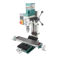
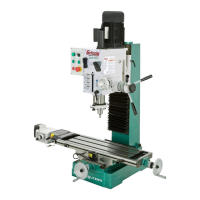
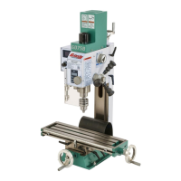
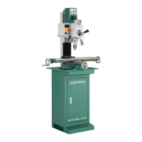
    Why Grizzly G0704 does not start?
    • C
      Christopher NguyenNov 19, 2025
      The Grizzly Drill might not start due to several reasons: 1. The circuit breaker on the machine might have tripped. To solve this, press the reset button on the motor junction box and reduce the load on the motor to prevent overheating. 2. The plug might be faulty or wired incorrectly. Ensure the plug is not damaged and is wired correctly. 3. The motor might be wired incorrectly. Ensure the motor wiring is correct. 4. The wall fuse or circuit breaker might be blown or tripped. Ensure the circuit size is correct and a short does not exist. Reset the breaker or replace the fuse. 5. The wiring might be open or have high resistance. Check for broken wires or disconnected/corroded connections, and repair or replace them as necessary. 6. The machine power switch might be at fault. Ensure ...
  • M
    Michelle RayNov 21, 2025
    What to do if my Grizzly G0704 Drill stalls?
    • R
      Rhonda GlassNov 21, 2025
      If your Grizzly Drill stalls or is overloaded, consider the following: * The feed rate or cutting speed may be too fast. Try decreasing the feed rate or cutting speed. * The wrong cutter type may be in use. Ensure you are using the correct cutter for the task. * The machine may be undersized for the task, or the tooling may be incorrect. Use smaller or sharper tooling, reduce the feed rate or spindle speed, and use cutting fluid if possible. * The motor connection may be wired incorrectly. Wire the motor correctly for the intended voltage. * The motor bearings may be at fault. Test by rotating the shaft; rotational grinding or a loose shaft requires bearing replacement. * The motor may have overheated. Clean off the motor, let it cool, and reduce the workload. * The motor it...
  • T
    Taylor StewartNov 23, 2025
    How to reduce vibration in Grizzly G0704 Drill?
    • D
      Denise BaileyNov 23, 2025
      To address vibration or noisy operation in your Grizzly Drill: * Check for loose motor or machine components. Inspect and replace any stripped or damaged bolts or nuts, and re-tighten them with thread-locking fluid. * Reduce the depth of cut if it is excessive. * Ensure the cutter or tooling is properly secured. * Replace or resharpen the cutter if it is dull or faulty. * If the bit is chattering, replace or sharpen it, index it to the workpiece, and use an appropriate feed rate and cutting RPM. * Ensure the machine is correctly mounted and sits evenly. Tighten or replace mounting bolts in the bench, and relocate or shim the machine if necessary. * Test the motor bearings by rotating the shaft; rotational grinding or a loose shaft indicates that bearing replacement is requir...

Summary

Important Update: New Motor and Stand Parts

New Motor Assembly Parts

Lists new parts for the motor assembly, including part numbers and descriptions.

Stand Assembly Parts

Lists new parts for the stand assembly, including part numbers and descriptions.

Introduction to the G0704 Mill;Drill

Manual Accuracy and Updates

Explains potential differences between the manual and machine, advising to check website or call support.

Contact Information for Support

Provides contact details for Grizzly Technical Support and Documentation Manager.

Machine Description and Operation

Describes the mill/drill's function and how it shapes metal workpieces.

Machine Identification

Component Identification

Diagram and list identifying key components of the G0704 machine.

Electronic Controls Identification

Control Panel Components

Diagram and list identifying electronic controls on the G0704.

Machine Data Sheet

Product and Shipping Specifications

Details dimensions, weight, and shipping information for the G0704.

Main Specifications Overview

Operation Information

Lists key operational specifications like spindle travel and drilling capacities.

Table Specifications

Details table dimensions, T-slot size, and other related measurements.

Spindle Specifications

Lists spindle taper, speed range, quill diameter, and bearings.

Construction Materials

Specifies materials used for machine components like headstock, table, and base.

Other Specifications

Includes country of origin, warranty, and sound rating.

Machine Features

Highlights features such as digital scales, forward/reverse switch, and coolant trough.

Section 1: Safety

General Safety Instructions

Provides warnings and safety instructions for operating machinery.

Additional Safety for Mill;Drills

Specific safety advice for operating mill/drills, including tool handling and spindle use.

Section 2: Power Supply

Power Supply Availability and Requirements

Details electrical requirements, voltage, phase, and current rating for the machine.

Grounding and Plug Requirements

Explains essential grounding procedures and plug types for safe operation.

Extension Cord Usage Guidelines

Recommends against, but provides guidelines for, using extension cords.

Section 3: Setup

Setup Requirements and Unpacking

Lists items needed for setup and instructions for unpacking the machine.

Inventory of Included Items

Lists all parts included with the machine for inventory.

Machine Cleanup Procedure

Step-by-step guide for removing rust preventative from the machine.

Site Considerations for Operation

Discusses weight load, space, environment, electrical, and lighting needs.

Moving and Placing the Machine

Instructions for safely moving and positioning the machine.

Mounting the Machine to the Floor

Provides methods for securing the machine to the floor.

Section 4: Operations

Operation Overview

Basic understanding of machine usage, controls, and operations.

Basic Controls and Functions

Explanation of key controls like handwheels, levers, and locks.

Digital Readout Unit Operation

Guide on using the digital readout for precise measurements.

Calculating Spindle Speed

How to determine the correct spindle speed for various materials.

Setting Spindle Speed and Direction

Instructions for setting spindle speed ranges and rotation direction.

Spindle Height Controls

Methods for adjusting spindle height using feed levers and knobs.

Drill Chuck Installation and Removal

Steps for installing and removing the drill chuck and arbor.

Loading and Unloading Tooling

Procedure for installing and removing cutting tools and collets.

Headstock Travel and Tilt

Adjusting headstock height and tilting the headstock for different operations.

Table Travel Operations

Using handwheels and locks for longitudinal and cross table movement.

Section 5: Accessories

Worktable with Angle

Description of a tilting worktable for supporting workpieces at various angles.

Horizontal Milling Table

Describes a cast-iron table for side-milling operations.

R-8 Vertical Collet Rack

Organizes R-8 collets, offering a convenient storage solution.

Boring Head Combo Set

Details a boring head set including arbor and boring bars.

End Mill Sets

Information on 2 and 4 flute TiN end mill sets.

Rotary Table

Features of a 4" rotary table for model makers.

Mobile Base

Description of a mobile base for easy machine movement.

Machine and Way Oil

Details a lubricant for preventing stick slip and chatter.

Section 6: Maintenance

Maintenance Schedule

Recommended daily, monthly, and biannual checks for machine upkeep.

Lubrication Procedures

Guide on lubricating sliding surfaces, leadscrews, and gears.

Cleaning Leadscrews

Steps to clean and lubricate vertical, cross, and longitudinal leadscrews.

Lubricating Vertical Leadscrew Bushing and Gears

Procedure for lubricating the vertical leadscrew bushing and pinion gears.

Section 7: Service and Troubleshooting

Troubleshooting Common Issues

Identifies symptoms, possible causes, and solutions for machine problems.

Adjusting Machine Gibs

Instructions for adjusting table and headstock gibs for smooth movement.

Adjusting Leadscrew Backlash

Procedure for reducing play in the X and Y axis leadscrews.

Digital Readout Unit Battery Replacement

Steps to replace the battery in the digital readout unit.

Motor Brush Inspection and Replacement

Guide for checking and replacing carbon brushes in the motor.

Section 8: Wiring

Wiring Safety Instructions

Essential safety precautions for working with electrical wiring.

Wiring Diagram

Schematic illustrating the machine's electrical connections.

Electrical Components Overview

Visual identification of electrical component locations within the machine.

Section 9: Parts Breakdown

Column Breakdown and Parts List

Diagram and list of parts for the machine's column assembly.

Electrical Box Breakdown and Parts List

Diagram and list of parts for the electrical enclosure.

Headstock Breakdown and Parts List

Diagram and list of components for the headstock assembly.

Chip Guard Breakdown and Parts List

Diagram and list of parts for the chip guard.

Labels Breakdown and Parts List

Diagram and list of all safety and identification labels.

Notes

Warranty Card

Warranty and Returns Information

Grizzly G0704 Specifications

General IconGeneral
Motor1 HP, 110V, Single-phase
Spindle TaperR-8
Max Spindle Speed2500 RPM
ModelG0704
CategoryDrill
Spindle Travel2"
Spindle Speed50-2500 RPM
Table Tilt45° Left/Right
Speed Range50-2500 RPM

Related product manuals