• 0-20 mA
• 4-20 mA.
Function of analog output
Actual speed
0 % 100 %
0 V 10 V
0 mA 20 mA
4 mA 20 mA
Sensor value
Minimum Maximum
0 V 10 V
0 mA 20 mA
4 mA 20 mA
Resulting setpoint
0 % 100 %
0 V 10 V
0 mA 20 mA
4 mA 20 mA
Motor load
0 % 100 %
0 V 10 V
0 mA 20 mA
4 mA 20 mA
Motor current
0 % 100 % 200 %
0 V 5 V 10 V
0 mA 10 mA 20 mA
4 mA 12 mA 20 mA
Limit-exceeded function
Output not active Output active
0 V 10 V
0 mA 20 mA
4 mA 20 mA
9.16 Controller (Controller settings)
The pumps have a factory default setting of gain (K
p
)
and integral time (T
i
).
However, if the factory setting is not the optimum
setting, you can change the gain and the integral
time:
• Set the gain within the range from 0.1 to 20.
• Set the integral-action time within the range from
0.1 to 3600 seconds. If you select 3600 seconds,
the controller functions as a PI controller.
Furthermore, you can set the controller to inverse
control.
This means that if you increase the setpoint, the
speed is reduced. In the case of inverse control, you
must set the gain within the range from -0.1 to -20.
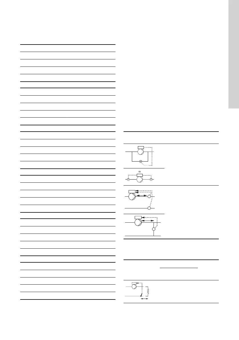
Guidelines for setting of PI controller
The tables below show the recommended controller
settings:
Constant
differential pressure
K
p
T
i
0.5 0.5
0.5
L1 < 5 m: 0.5
L1 > 5 m: 3
L1 > 10 m: 5
L1: Distance in metres between the pump and the
sensor.
Constant
temperature
K
p
T
i
Heating
system
Cooling
system
0.5 -0.5 10 + 5L2
61
English (GB)
 Loading...


