Pos. Description
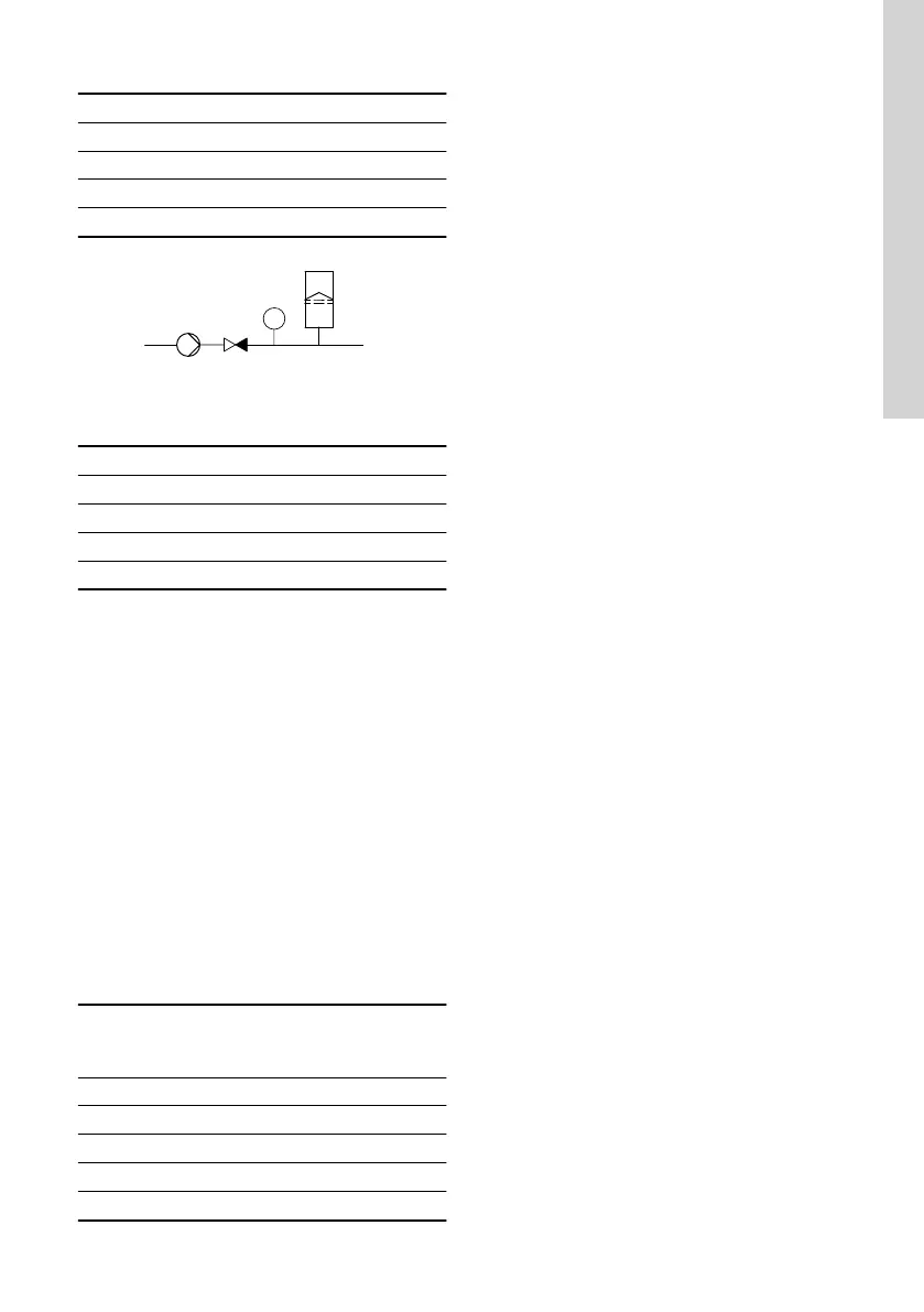
1 Non-return valve
2 Pump
3 Pressure sensor
4 Diaphragm tank
TM038583
Position of the non-return valve and pressure
sensor in a system with a positive inlet pressure
Pos. Description
1 Pump
2 Non-return valve
3 Pressure sensor
4 Diaphragm tank
Set minimum flow
Set the minimum flow rate (Q
min
) in this display. This
setting determines at which flow rate the system is to
change from continuous operation at constant
pressure to start-stop operation. The setting range is
5 to 30 % of the rated flow rate.
Factory setting
See the section on factory settings.
Diaphragm tank volume
The stop function requires a diaphragm tank of a
certain minimum size. Set the size of the installed
tank in this display.
To reduce the number of start-stops per hour or to
reduce the ΔH, install a larger tank.
Install the tank immediately after the pump. The
precharge pressure must be 0.7 × actual setpoint.
Recommended diaphragm tank size:
Rated flow rate of
pump
[m
3
/h]
Typical diaphragm tank
size
[litres]
0-6 8
7-24 18
25-40 50
41-70 120
71-100 180
Factory setting
See the section on factory settings.
Related information
9.58 Factory settings for Grundfos GO
9.24 Stop at min. speed
This stop function can be utilised in for example
constant level applications where a boost of pressure
is not needed. It is a different type of stop function
than low-flow stop but the purpose is the same. The
pump stops if there is no or low consumption.
This function monitors the speed of the pump. When
the PI-controller has forced the speed of the pump to
minimum according to the feedback value, the pump
stops after a set period of time. It remains stopped
until the feedback value starts to drop and the PI-
controller starts the pump again.
• Enable Stop at min. speed
Enables the function Stop at min. speed.
• Delay
The delay time the pump must be running at
minimum speed before it stops.
• Restart speed
Speed in percentage when the pump must start
again, hysteresis. It must be set higher than the
minimum speed of the pump.
69
English (GB)
 Loading...


