9.25 Pipe filling function
This function is typically used in pressure-boosting
applications and ensures a smooth startup of systems
with for instance empty pipes.
Startup takes place in two phases. See the figure
below.
1. Filling phase. The pipes are slowly filled with
water. When the pressure sensor of the system
detects that the pipes have been filled, phase two
begins.
2. Pressure build-up phase. The system pressure is
increased until the setpoint is reached. The
pressure build-up takes place over a pressure
build-up time. If the setpoint is not reached within
a given time, a warning or an alarm can be given,
and the pumps can be stopped at the same time.
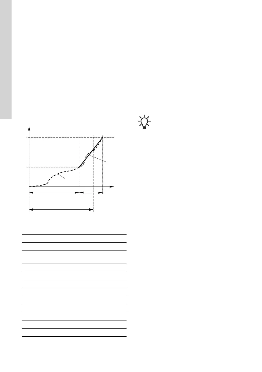
TM039037
Filling and pressure build-up phases
Pos. Description
1 Filling phase (constant-curve operation)
2
Pressure build-up phase (constant-pressure
operation)
3 Setpoint
4 Filling pressure
5 Actual value
6 Setpoint ramp-up
7 Filling time
8 Pressure build-up time
9 Maximum filling time
P Pressure
t(s) Time (sec)
Setting range
• Filling speed. Fixed speed of the pump during
the filling phase.
• Filling pressure. The pressure that the pump
must reach before the maximum filling time.
• Max. filling time. The time in which the pump
must reach the filling pressure.
• Max. time reaction. Reaction of the pump if the
maximum filling time is exceeded:
- warning
- alarm (pump stops).
• Pressure build-up time. Ramp time from when
the filling pressure is reached until the setpoint
must be reached.
When you activate this function, the
function always starts when the pump has
been in operating mode Stop and is
changed to Normal.
Factory setting
See the section on factory settings.
Related information
9.58 Factory settings for Grundfos GO
9.26 Pulse flowmeter (Pulse flowmeter
setup)
You can connect an external pulse flowmeter to one
of the digital inputs in order to register the actual and
accumulated flows. Based on this, you can also
calculate the specific energy.
To enable a pulse flowmeter, set one of the digital-
input functions to Accumulated flow and set the
pumped volume per pulse.
Factory setting
See the section on factory settings.
Related information
9.12 Digital inputs
9.58 Factory settings for Grundfos GO
9.27
Ramps
The ramps determine how quickly the product can
accelerate and decelerate during start and stop or
setpoint changes.
You can make the following settings:
• acceleration time, 0.1 to 300 s
• deceleration time, 0.1 to 300 s.
The times apply to the acceleration from 0 rpm to a
fixed maximum speed and the deceleration from a
fixed maximum speed to 0 rpm, respectively.
At short deceleration times, the deceleration of the
product may depend on load and inertia as there is
no possibility of actively braking the product.
70
English (GB)

 Loading...


