English (GB)
14
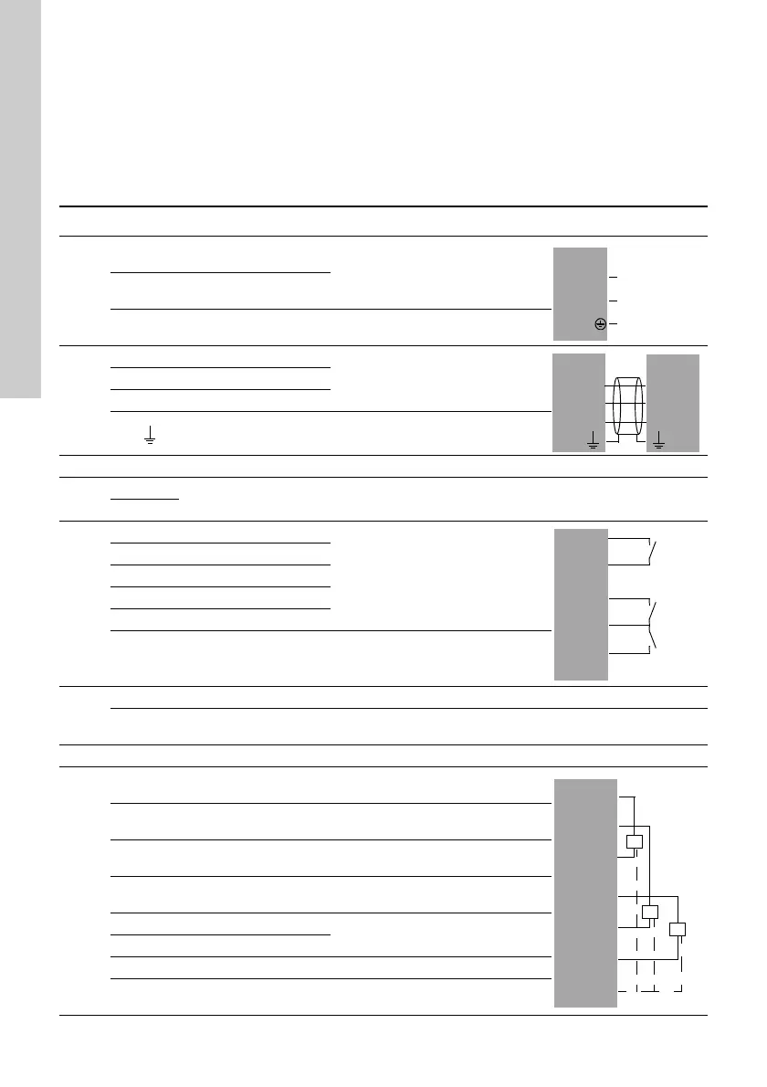
10. Overview of inputs and outputs
DI: Digital input
DO: Digital output
AI: Analog input
NC: Normally closed contact
NO: Normally open contact
C: Common.
Position numbers, see fig. 17.
Group Terminal Designation Data Diagram
1
L
Connection to phase
conductor
1 x 100-240 VAC ± 10 %, 50/60 Hz
N
Connection to neutral
conductor
PE
Connection to
protective earth
2
A1 RS-485 A
GENIbus
(Fix the screen with a cable clamp.)
Y1 RS-485 GND
B1 RS-485 B
Functional earth
3 Connection to external fieldbus, see installation and operating instructions for the CIM module.
4
0 V
Connection to battery Backup battery
+12 VDC
5
10 DI1
Digital input
11 GND
12 DI2
13 GND
14 DI3
All terminals (except mains terminals) must only be connected to
voltages not exceeding 16 V
rms
and 22.6 V
peak
or 35 VDC.
6
Ethernet RJ45
External computing devices connected to the Ethernet connection must
comply with the standards IEC 60950 and UL 60950.
7 GENIbus Service connection
8
47 +24 V
Supply to sensor.
Short-circuit-protected 30 mA
50 +24 V
Supply to sensor.
Short-circuit-protected 30 mA
51 AI1
Input for analog signal,
0-20/4-20 mA or 0-10 V
53 +24 V
Supply to sensor.
Short-circuit-protected 30 mA
54 AI2
Input for analog signal,
0-20/4-20 mA or 0-10 V
57 AI3
58 GND*
All terminals (except mains terminals) must only be connected to
voltages not exceeding 16 V
rms
and 22.6 V
peak
or 35 VDC.
 Loading...