65
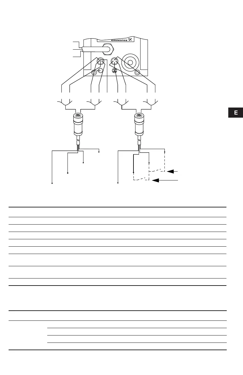
3.6 Esquema de conexiones
Fig. 3 Esquema de conexiones
Entrada de control:
1 = Contacto para señal de impulsos
2 = Contacto para on/off externo
Entrada de nivel:
Relé de alarma (sólo versión de control "AR")
TM01 8422 0603
2
3
1
4
1
3
4
5
1
3
4
5
3
1
4
2
2
"NO" negro
"NC" azul
"Com" marrón
Tanque vacío
Nivel bajo
Cable de control,
ver la siguiente tabla
Cable de nivel,
ver la siguiente tabla
Número / color 1 / marrón 2 / blanco 3 / azul 4 / negro 5 / gris Descripción
Función
Manual 2 2
Impulso 1 1
Impulso + on/off externo 1 1 + 2 2
Analógico – + Señal mA
Analógico +
on/off externo
22–+ Señal mA
Temporizador +
on/off externo
22
Batch (lote) 1 1
Número / color 1 / marrón 2 / blanco 3 / azul 4 / negro
Función
Nivel bajo Nivel bajo
Tanque vacío Tanque vacío
Nivel bajo Tanque vacío Nivel bajo + tanque vacío
Control de dosificación Control de dosificación
Grundfos.bk Page 65 Wednesday, May 21, 2008 11:21 AM