27
English (US)
See table, fig. 33.
The table shows the suggested controller settings:
Fig. 33 Suggested controller settings
1)
Heating systems are systems in which an increase in pump
performance will result in a rise in temperature at the sensor.
2)
Cooling systems are systems in which an increase in pump
performance will result in a drop in temperature at the sensor.
L
2
= Distance in [m] between heat exchanger and sensor.
Proceed as follows:
1. Increase the gain (K
p
) until the motor becomes unstable.
Instability can be seen by observing if the measured value
starts to fluctuate. Furthermore, instability is audible as the
motor starts hunting up and down.
Some systems, such as temperature controls, are
slow-reacting, meaning that it may be several minutes before
the motor becomes unstable.
2. Set the gain (K
p
) to half the value of the value which made the
motor unstable. This is the correct setting of the gain.
3. Reduce the integral time (T
i
) until the motor becomes
unstable.
4. Set the integral time (T
i
) to twice the value which made the
motor unstable. This is the correct setting of the integral time.
General rules of thumb:
• If the controller is too slow-reacting, increase K
p
.
• If the controller is hunting or unstable, dampen the system by
reducing K
p
or increasing T
i
.
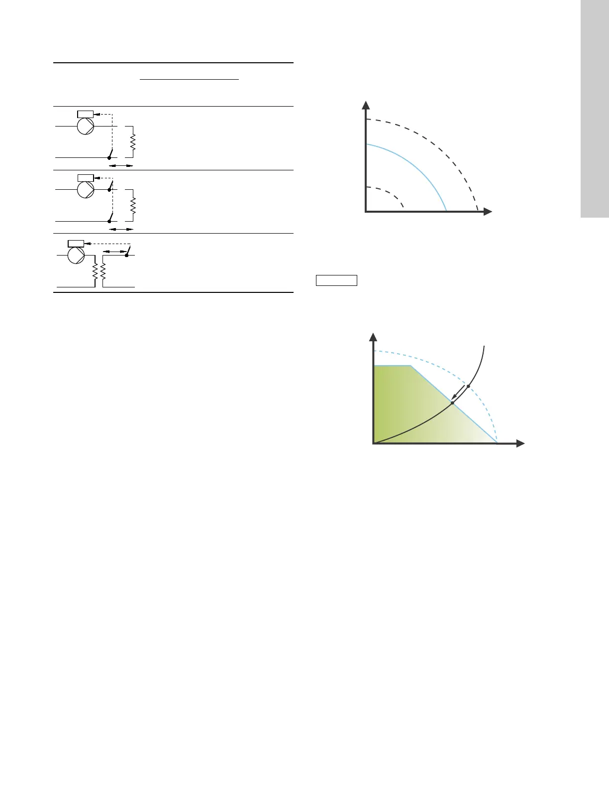
13.3.7 Constant curve
The pump can be set to operate according to a constant curve,
like an uncontrolled pump. See fig. 34.
The desired speed can be set in % of maximum speed in the
range from 25 to 100 %.
Fig. 34 Constant curve
Fig. 35 Power and pressure limitations influencing the max.
curve
System/application
K
p
T
i
Heating
system
1)
Cooling
system
2)
0.5 - 0.5 10 + 5L
2
-0.5 10 + 5L
2
0.5 - 0.5 30 + 5L
2
TM05 2446 0312
Depending on the system characteristic and the
duty point, the 100 % setting may be slightly
smaller than the pump's actual max. curve even
though the display shows 100 %. This is due to
power and pressure limitations built into the
pump. The deviation varies according to pump
type and pressure loss in the pipes.
TM05 3041 1212
Max. curve
Limited
max. curve
Actual duty point

 Loading...


