16 of 36© 2009 D 664 - 07/09
Melt / Idle Demand
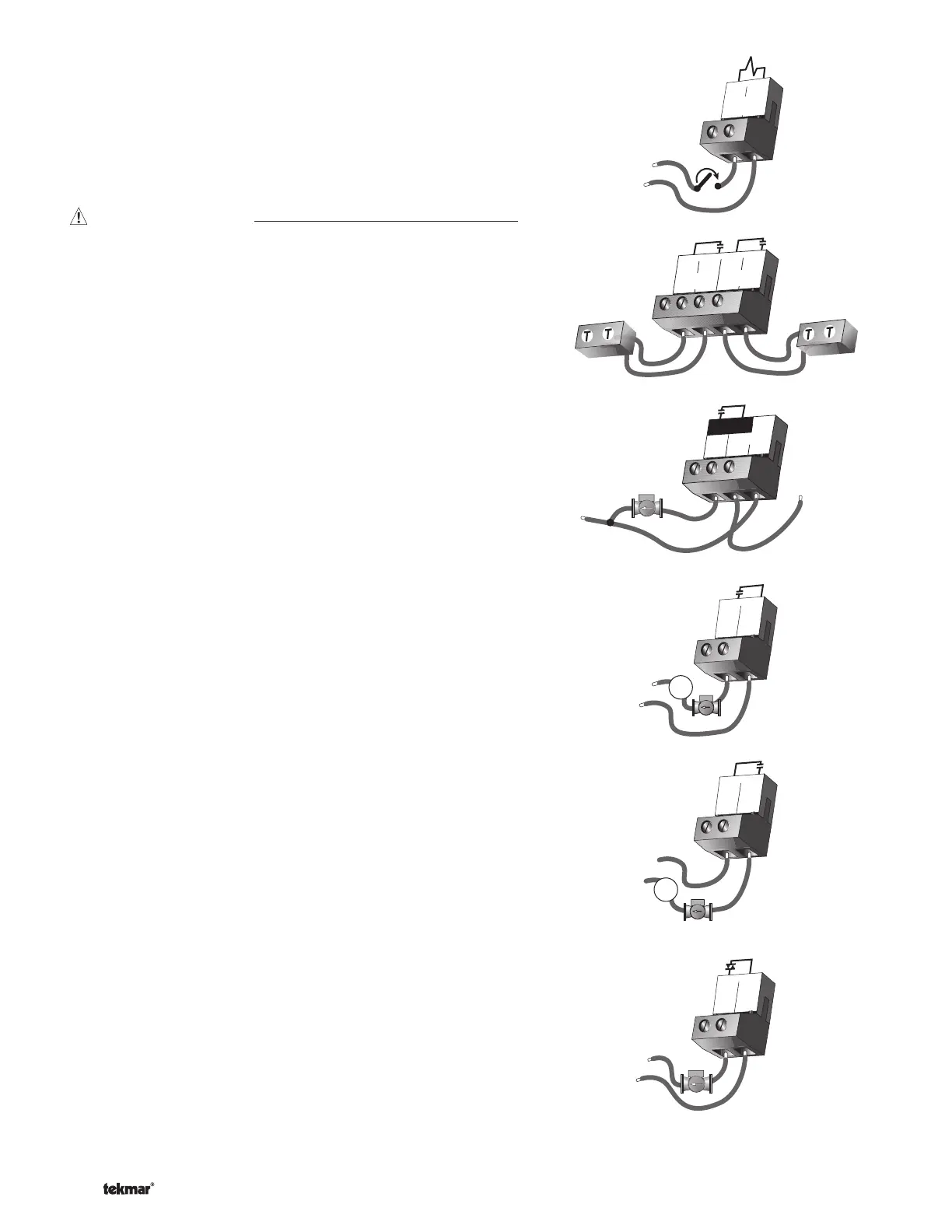
To generate a melt demand or idle demand, a voltage between
24 V (ac) and 230 V (ac) must be applied across the Melt / Idle
Demand terminals (19 and 20).
Output Connections
Boiler Contacts
The Stage 1 and Stage 2 terminals (21, 22 and 23, 24) are isolated
outputs in the 664. There is no power available on these terminals
from the control. These terminals are used as a switch to either make
or break the boiler circuit. When the 664 requires the boiler(s) to fi re, it
closes the contact between terminals 21 and 22 and / or 23 and 24.
System Pump Contact (Sys P1)
The Sys P1 output terminal (28) on the 664 is a powered output.
When the relay in the 664 closes, 115 V (ac) is provided to the Sys P1
terminal (28) from the Power L terminal (29). To operate the system
pump, connect one side of the system pump circuit to terminal 28
and the second side of the pump circuit to the neutral (N) side of the
115 V (ac) power supply.
Zone Pumps and Zone Valves
The zoning outputs are isolated terminals in the 664. There is no
power available on these terminals from the control.
If zone 1 is used, connect the zone pump or zone valve circuit to the
Com Zn and Zn 1 terminals (26 and 25).
If zone 2 is used, connect the zone pump or zone valve circuit to the
Com Zn and Zn 2 terminals (26 and 27).
Variable Speed Injection Pump
The 664 can vary the speed of a permanent capacitor, impedance
protected or equivalent pump motor that has a locked rotor current
of less than 2.4 A. Most small wet rotor circulators are suitable as
described in Essay E 021. The 664 has an internal overload fuse which
is rated at 2.5 A 250 V (ac). Contact your tekmar sales representative
for details on the repair procedures if the fuse is blown.
If a variable speed injection pump is used, connect one of the wires
from the variable speed injection pump to the Opn / Var terminal (3)
on the 664. Connect the Pwr Mix terminal (4) to the live (L) side of
the 115 V (ac) power source. The other wire on the variable speed
injection pump must be connected to the neutral (N) side of the
115 V (ac) power supply.
19
20
Melt / Idle
Demand
24 to 230 V (ac)
L
N
22
21
23
24
Stage
1
Stage
2
Sys
P1
115 V (ac)
N
L
Power
30
L
N
29
28
25
Zn
1
26
Com
Zn
M
24 to 230 V (ac)
L
N
OR
26
Com
Zn
27
Zn
2
M
24 to 230 V (ac)
L
N
OR
3
4
Pwr
Mix
Opn/
Var
115 V (ac)
N
L

 Loading...


