Functions
MAGNA3
4
31
The electrical signal for the input can be 0-10 V or 4-20
mA. You can change the selection of the electrical
signal (0-10 V or 4-20 mA) on the operating panel or
with Grundfos GO.
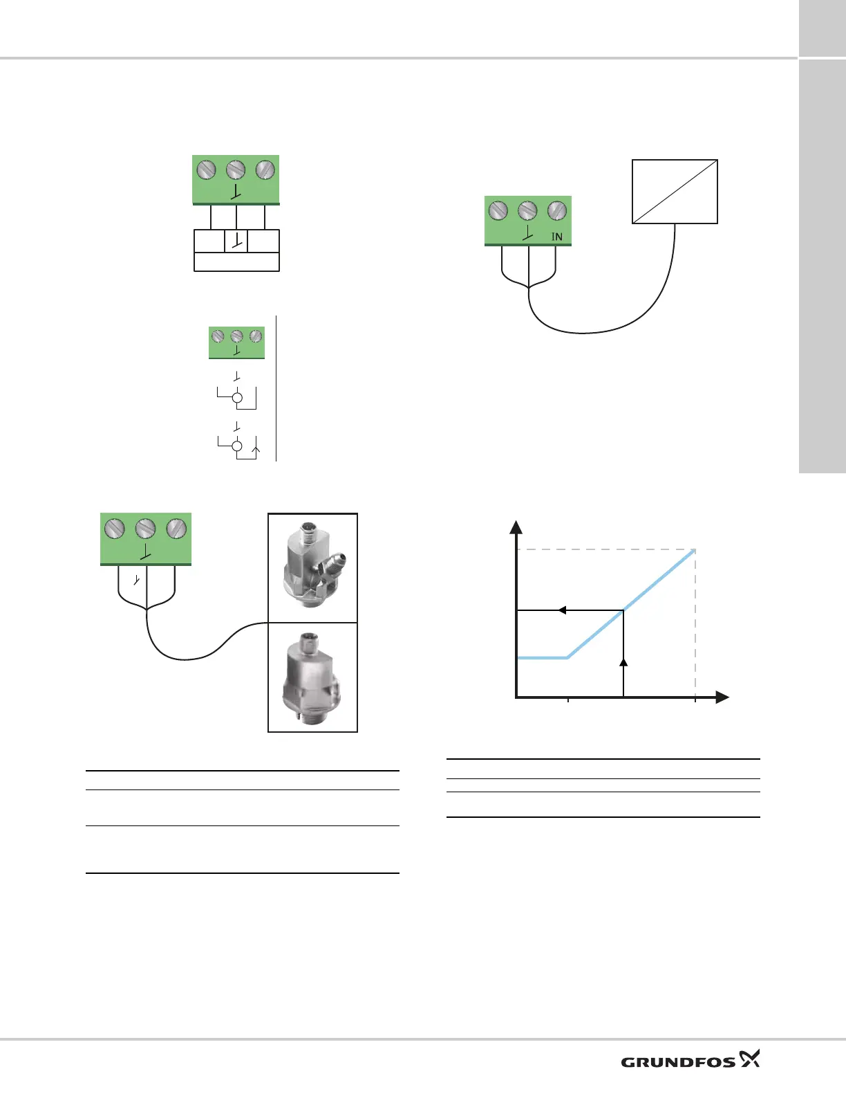
Fig. 42 Analog input for an external sensor or control
Fig. 43 Wiring, analog input
Fig. 44 Examples of external sensors
For further details, see External Grundfos sensors,
page 59.
External control system
The analog input can be used for an external signal for
the control from a BMS system or similar control
system.
Fig. 45 Example of an external signal for the control via
BMS or PLC
External setpoint function
You can use the analog input to influence the setpoint
externally. Here, a 0-10 V or 4-20 mA signal controls
the pump speed range in a linear function. The range
of control depends on the minimum speed, power and
pressure limits of the pump. See figs 46 and 47.
Fig. 46 External setpoint function, 0-10 V
Fig. 47 Control range and setpoint
The external setpoint function operates differently,
depending on the model. For model A,B and C, the
maximum speed is often obtained at voltages lower
than 10 V as the span of control is limited.
In models newer than A,B, and C, the internal scaling
has been optimized to make the dynamic area bigger,
thus giving a better control of the pump speed when
using the external setpoint function.
The same applies if the pump is receiving a setpoint
from Building Management Systems.
TM05 3221 1112TM05 3343 2313
TM06 7237 3416
Pos. Sensor type
1
Differential-pressure transmitter,
Grundfos type DPI V.2
1/2" connection and 4-20 mA signal.
2
Relative-pressure transmitter.
Combined temperature and pressure sensor, Grundfos
type RPI T2.
1/2" connection and 0-10 V signal.
Max.
250 V AC
2 A AC1
Min.
5 V DC
20 mA
Max.
24 V DC
22 mA
0 - 10 V DC
4 - 20 mA
I
IN
24V
Vcc
Signal
Vcc
Signal
TM05 2888 0612
TM06 9149 2117
Control
0-2 V (0-20 %) Resulting setpoint is equal to minimum.
2-10 V (20-100 %)
Resulting setpoint is between minimum and
user setpoint.
V
1020
H
(user setpoint)
Analog input
Resulting
setpoint

 Loading...


