Construction
MAGNA3
6
36
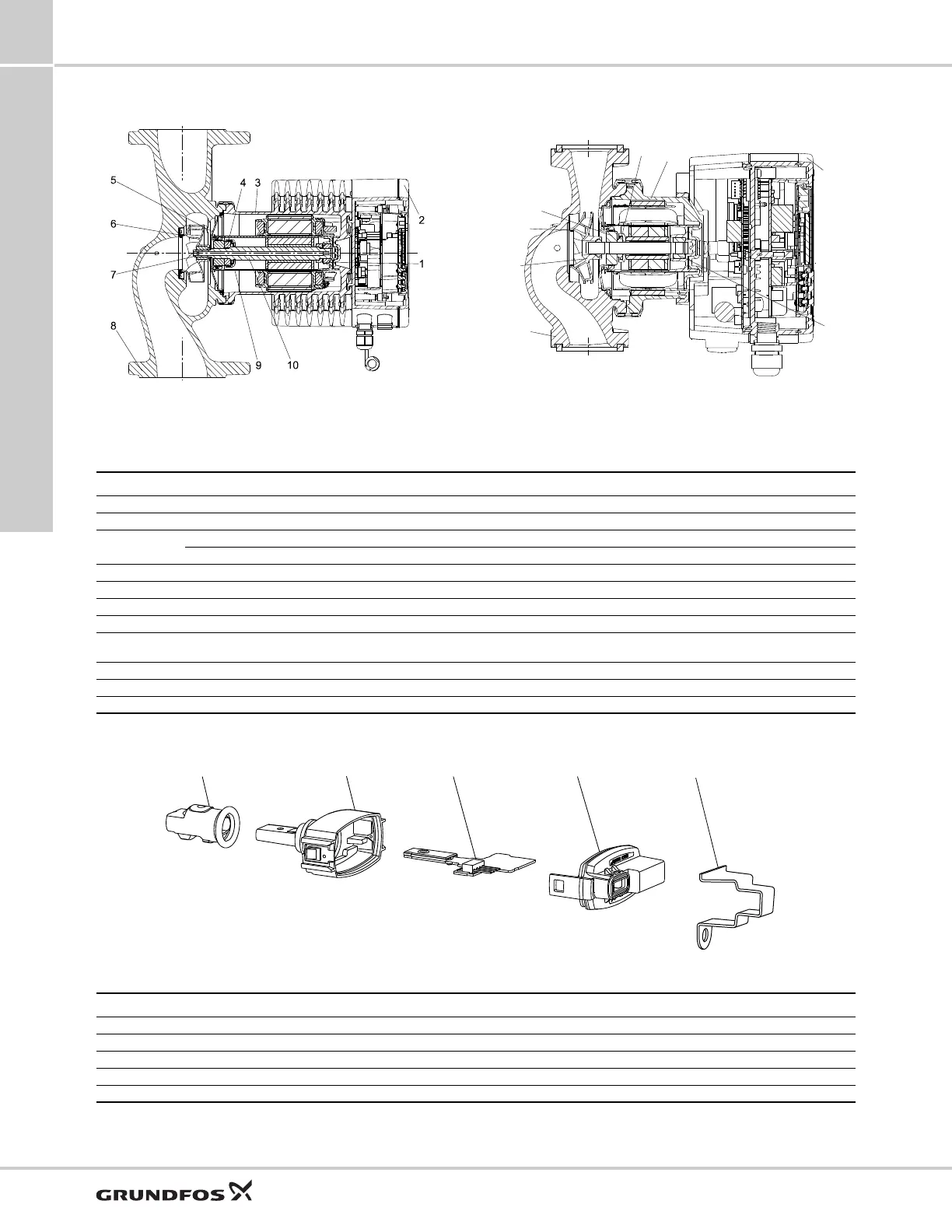
Sectional drawing
Fig. 49 Terminal-connected version Fig. 50 Wire-to-wire-connected version
Material specification
See fig. 49.
Sensor drawing
Fig. 51 Sensor
TM05 2319 0312
TM07 1970 2518
Pos. Component Material Grade
1 Outer bearing ring Aluminium oxide
2 Control box Polycarbonate
3
Stator housing Aluminium
O-rings EPDM
4 Thrust bearing Aluminium oxide/carbon
5 Bearing plate Stainless steel AISI 304 (EN 1.4301)
6 Neck ring Stainless steel AISI 304 (EN 1.4301)
7 Impeller PES
8 Pump housing Cast iron/stainless steel
ASTM A48 class 35B/AISI 316
(EN 1561 EN-GJL-250/EN 1.4408)
9 Rotor can PPS
10 Shaft Ceramic (wire-to-wire-connected versions)
10 Shaft Stainless steel (terminal-connected versions) AISI 316L (EN 1.4404)
TM06 9250 2117
4321
5
Pos. Component Material Grade
1 Sealing cap EPDM
2 Housing PPS
3 Printed-circuit board -
4 Cover snap-on PA/TPV
5 Bracket for sensor Stainless steel AISI 304 (EN 1.4301)

 Loading...


