18
APCD-500, rev10
APCD-500
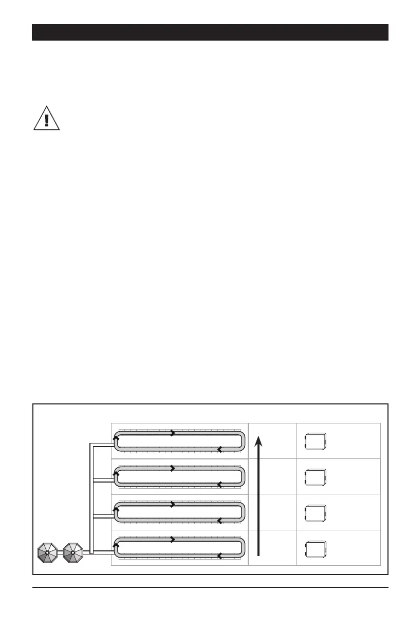
4.4.3. Filling Independent Chain Disk
Systems with a Common Bin Auger us-
ing Continuous Feed Distribution Mode
The common bin auger must be con-
nected to the master APCD module!
1. Beginning the Filling Process — The fill-
ing process starts at the end of the previous
cycle (refer to point 7 below to see when a
cycle ends).
2. Emptying the Bin Auger and Chain Disk
Systems — When the “Continuous Delay” has
elapsed, the controller activates all drive
units during the “Purge Time” and launches
the “A u g e r D e l a y” . When the “A u g e r D e l a y” has
elapsed, the bin auger starts sending feed to-
wards the Chain Disk Systems. Normally, the
“Purge Time” must be longer than the “A u g e r
Delay” to prevent feed from accumulating at
the end of the bin auger.
3. Filling the First Chain Disk System —
When the “Purge Time” is over, all drive units
stop except for the first Chain Disk System
to be filled: the master Chain Disk System.
4. The Chain Disk System is Full — The
controller knows the Chain Disk System is
full when the proximity sensor located at its
end detects feed for 5 seconds without inter-
ruption. When feed is detected, the drive unit
of this Chain Disk System stops.
5. Filling the Chain Disk Systems One by One
— Each time a Chain Disk System gets full, its
drive unit stops running and the next Chain
Disk System starts being filled (Chain Disk
Systems are being filled in numerical order).
6. The Last Chain Disk System is Full — When
the last Chain Disk System is full (i.e., the
slave Chain Disk with the highest ID #), all
drive units are off and the bin auger stops
bringing feed into the system.
7. Next cycle — The next feed cycle starts
when the last Chain Disk System gets empty:
a) If the proximity sensor is mounted in the
last drop, the next cycle starts when the
proximity sensor stops detecting feed.
b) If the proximity sensor is on the Mas-
ter Chain Disk System line after the last
drop, the new cycle starts if no feed is
detected after 2 delays: “Continuous Feed
Delay” + “Bypass Delay” (the “Continuous
Feed Delay is the amount of time required
for the animals to eat the feed).
Back to step 1.
Last
Third
Second
First
APCD-500-S
ID 3
APCD-500-S
ID 2
APCD-500-S
ID 1
APCD-500
MASTER
Chain Disk Systems Filling Order Controller & ID#
Bins