7
APCD-500, rev10
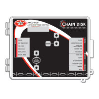
APCD-500
2.2. Adjusting a Parameter
Use the arrow keys to select the parameter
that needs to be adjusted. When it is selected,
press MODIFY to display the pop-up window
for adjusting the parameter. Now, use the ar-
row keys to modify the parameter’s value and
then press the MODIFY button again to validate
the change.
3. MOUNTING INSTRUC-
TIONS
3.1. Mounting the Control-
ler on the Wall
Remove the four screws in the front cover
and lift the cover. Remove the black caps lo-
cated on the three mounting holes. Mount the
enclosure to the wall using three screws. Be
sure the electrical knockouts are at the bot-
tom of the enclosure in order to prevent water
from entering the controller. Insert the screws
into the mounting holes and tighten. Fasten
the black caps onto the mounting holes.
3.2. Connections
To connect the controller, refer to the wiring
diagram enclosed with this user’s manual.
Use the electrical knockouts provided at the
bottom of the enclosure. Do not make ad-
ditional holes in the enclosure, particularly
on the side of the enclosure when using a
computer communications module.
All wiring must be done by an au-
thorized electrician and must comply
with applicable codes, laws and regu-
lations. Be sure power is off before
doing any wiring to avoid electrical
shocks and equipment damage.
• Do not install rigid conduit into electrical
knockouts. Only nylon cable glands are per-
mitted for cable or wire fastening.
• The controller has no power-on switch.
An external switch or circuit breaker shall be
included in the building installation to inter-
rupt power to L and N electric power lines. It
shall be in close proximity to the equipment
and within easy reach of the operator. It shall
be marked as the disconnecting device for
the equipment.
• The main supply circuit breaker for Chain
Disk motor (L1/L2 POWER IN) shall be no
larger than 20 A.
• Wire gage used for mains supply (L1/L2
POWER IN) and Chain Disk motor shall be at
least 12 AWG.
• Separate circuit breaker shall be used for
auger motor.
• The mains supply breaker for auger motor
shall be 15 A.
• Wire gage used for Flex-Flo auger motor
shall be at least 14 AWG.
Safety may be jeopardized if the equipment
is used in a manner not specified by the
manufacturer.