33
APCD-500, rev10
APCD-500
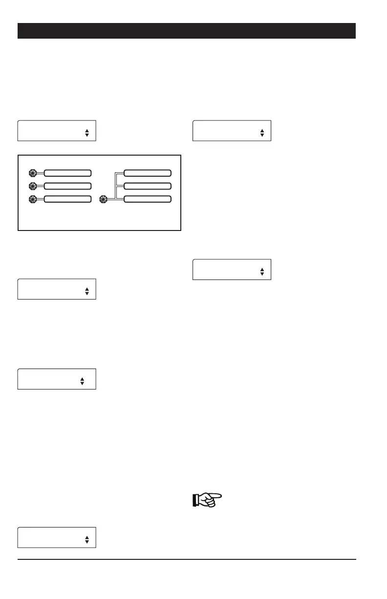
Common Auger — If independent Slave Chain
Disk Systems are enabled above, specify if
all Chain Disk Systems have their own bin
auger or if they share a common auger. *This
parameter is available if at least 1 independent slave
Chain Disk System is enabled above.
Use Common auger
Yes
Independent
Bin Augers
Common
Bin Auger
Proxy Switch — Select “Yes” if proximity
sensors are used to detect the presence of
feed in the system.
Use Proxy
Switch? Yes
Proxy Switch Status — Choose the normal
contact status of all proximity sensors in use:
Normally Opened (NO) or Normally Closed
(NC). *This parameter is available if proximity
sensors are enabled.
Proxy Switch
Normally Open
Feed Sensor Bypass — When a feed cycle
starts, some feed leftovers from the previous
cycle are likely to remain. The “Feed Sensor
Bypass Delay” allows ignoring the presence
of these leftovers at the beginning of a feed
cycle. Set this delay separately for each
Chain Disk System in use: Mstr = Master
Chain Disk System, S1,= Slave 1, S2,=
Slave 2, etc. It ranges from 0 to 30 minutes.
* This parameter is available if a proximity sensor
is enabled above and if the system does not use the
common bin auger.
Feed Sensor Mstr
Bypass 0:30m:s
Continuous Feeding / Timed Feeding — Se-
lect “Yes” to use the continuous feeding
mode; select “No” to use timed feed distribu-
tion (see sec. 4.3). *The controller automatically
enables the proximity sensor when the continuous
feeding mode is enabled.
Continuous
Feeding? No
Proxy Switch in Drop Tube ? — This parame-
ter tells where the proximity sensor is located
when using the continuous feed distribution
mode. Select “Yes” if it is mounted in the
last drop tube to be filled in each Chain Disk
System or select “No” if it is located on the
Chain Disk System line after the last drop
and before the fill hopper. * This parameter
is available if the “Continuous feeding” and “Use
Proxy” options are enabled.
Prox Switch in
drop tube? No
Continuous Feeding Delay — This delay is ex-
clusively used in the continuous feeding mode.
Depending on the location of the proximity
sensor, this delay takes a different meaning
(see below). * This parameter is available if the
continuous feeding mode is enabled above.
1. If the proximity sensor is mounted in the
last drop tube to be filled in each Chain Disk
System, the “Continuous Feeding Delay” tells
when to start a feed cycle from the moment
the drop tube is empty (no feed is detected
in the last drop).
2. If the proximity sensor is mounted on the
Chain Disk System line after the last drop and
before the fill hopper, the “Continuous Feeding
Delay” is an estimation of time it will take for
the animals to eat the feed.
The main difference between both
possibilities is that in the first case,
the system is considered as being
empty when the proximity sensor
stops detecting feed; in the second