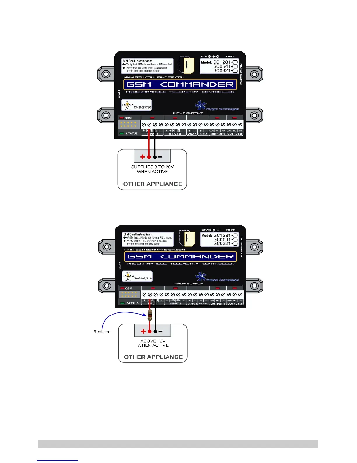
You may need an input to activate when power is supplied from some other unit. A good example
will be a burglar alarm that applies power to the wires going to the siren. In such a case, it will be a
simple matter of connecting the positive wire to the +IN input, and the negative wire to the –IN
input.
Please keep in mind that these inputs are designed for 3V to 20V operation. If you require to connect
a voltage above 20V to these terminals, you should connect a resistor in series with the input, as
shown below.
Input Voltage range Required Series resistor:
20V – 40V DC 1K ohm
The + and – terminals are connected to the input power supply of the GSM Commander.
If the power supply is 14V, the voltage at the + and – terminals will be slightly less at about 13.8V
(due to an internal series diode for reverse polarity protection).
© Polygon Technologies. All rights reserved Page 12