17. 4-20MA ANALOG APPLICATION NOTE
Goal:To connect a 4-20mA sensor to your GSM Commander.
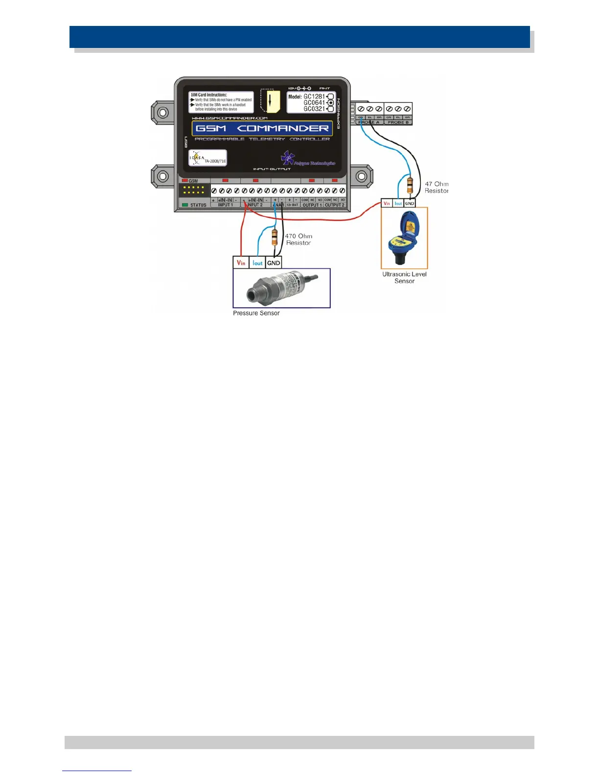
GSM Commander Wiring:
Connect a wire from the (+) terminal(14V) of any Input from the GSM Commander to the supply
voltage input of the sensor. Then connect a wire from the output(4-20mA) of the sensor to the (+)
terminal of the Analog Input. Connect GND of the sensor to the (–) terminal of the Analog Input. Very
important, connect a 470 ohm resistor in parallel with the output signal of the sensor and GND as
illustrated above. This resistor together with the internal voltage divider resistors ensures that the
voltage across the Analog Input is between 0 – 10,8V as required. To be more specific, the minimum
voltage would be 1.88V when the output signal is 4mA, and the maximum voltage would be 9,4V
when the output signal is 20mA.
Further Clever Ideas (The MacGyver Move):
The possibility exists, that the Temperature Interface module could be used to make an extra 2x
Analog Inputs available. The slight drawback would be that you would have to make use of the
temperature monitoring features in the software to control these inputs. Thus a 4mA output signal
of the sensor would be equivalent 19°C and a 20mA output signal would be equivalent to 94°C.
Convert this temperature reading in the Setup Software in order to SMS a “value” instead of a
temperature reading. Eg: If temperature at probe A stays below 36C, then send “Alarm: 200-Lit in
reservoir” via SMS to…... It may not be pretty, but it works.
© Polygon Technologies. All rights reserved Page 49