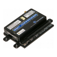
Here is a schematic of the input circuit used on the GSM Commander:
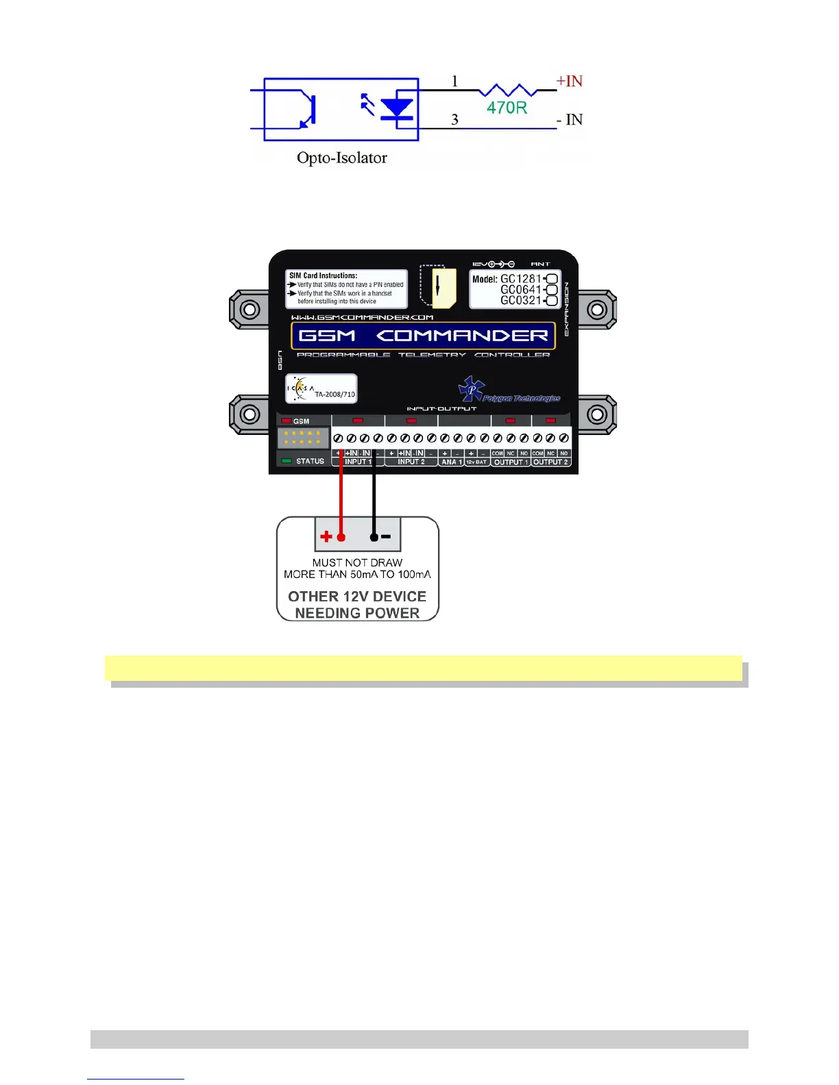
Drawing power for external hardware from the power terminals on the input:
One should not attempt to draw more than 50-100mA in total from the power terminals at the inputs
on the GSM Commander. For each expansion unit, the same applies.
5.9. Outputs
The GSM Commander itself provides 2 x 8A (DC) Relay outputs. The number of outputs can be
expanded by the addition of Expansion modules, up to a maximum of 32 outputs*. Each of these
inputs each have 3 terminals associated with them:.
Each of these inputs each have 3 terminals associated with them:
COM – Common Terminal
N/C – Normally Closed Terminal
N/O – Normally Open Terminal
When the output is off, the COM and N/C terminals will be internally connected to each other.
When the output is on, the COM and N/O terminals will be internally connected to each other.
Note that there are small LED indicators above the output terminals, that will show if the output is
ON or OFF (if the LED is on, then the output is also on).
* Model Dependent (See Feature Matrix in Section 2)
© Polygon Technologies. All rights reserved Page 13