16
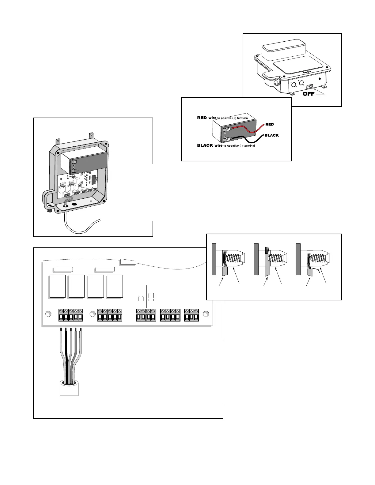
Step 17:
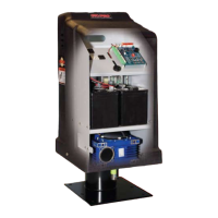
Turn the control box OFF. Remove the front cover of the control box. Slide
the battery into position with the terminals to the left. NEVER insert battery
with the terminals to the right. Be sure the battery fits snugly in the control
box. Connect the battery lead wires to the battery, red wire to (+) terminal,
black wire to (-) terminal. Pay careful attention to the color of the wire (not
the connectors). If the wires are connected incorrectly, it will damage the
control board.
HINT: a dab of household petroleum jelly on each
terminal will help prevent corrosion.
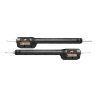
Step 20:
Be sure the power switch is OFF before continuing.
S1
S2
S3
S4
S5
RED
BLK
RED
BLK
SOLAR
TRANSFORMER
15 15
RED
BLK
GRN
ORG
BLU
RED
BLK
GRN
WHT
BLU
ORG
GRN
RED
BLK
GRN
ORG
BLU
RED
BLK
RED
BLK
FIRST OPERATOR SECOND OPERATOR POWER IN ACCESSORY GTO RECEIVER
15 amp 15 amp
PRO 2000 Board
Terminal Blocks
TRANSFORMER
SOLAR
RED
BLACK
GREEN
ORANGE
BLUE
RED
BLACK
GREEN
ORANGE
BLUE
Power Cable
from First Operator
Step 18:
Feed the free end of the 6' power cable upward through the power cable
strain relief (attached to the power cable for shipping) on the bottom of the
control box. Pull 6”-8” of wire into the control box and tighten the strain
relief to secure power cable. The free end of the power cable can be cut to
length, if necessary.
Step 19:
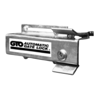
Carefully strip off the outer shield of the power cable and then strip 1/4" off the ends of each
individual wire and twist tightly. Attach these ends to the control board at the terminal strip
marked "FIRST OPERATOR".
Insert the RED wire into the terminal marked RED, BLACK wire to BLK and so on.
Tighten set screws against exposed end of wires. A dab of household petroleum jelly on each
terminal will help prevent corrosion.
Correct
Wrong Wrong
Wire
Terminal
Block
Terminal
Block
Terminal
Block
Wire Wire