9
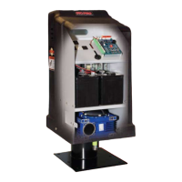
Receiver
Run up to 1000' of low
voltage wire to control
box from transformer.
(wire not included)
120 Volt Indoor
Transformer
(Surge Protector,
not supplied)
PVC conduit (not included) to protect wire from lawnmowers and weedeaters.
Control Box with Battery
Power Cable
CAUTION
AUTOMATIC GATE
STAND CLEAR
1-800-543-GATE
®
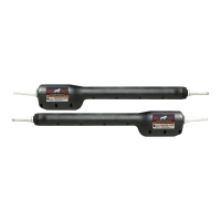
Closed Position Positive Stop Plate
Gate Bracket
Post Bracket Assembly
GTO/PRO 2000
Preparing the Gate
Step 1:
The gate must be in proper working order, plumb, level and swinging freely on its hinges. Do not use wheels on gate. The
gate must move smoothly and evenly throughout its swing, without binding or dragging on the ground. Gates over 250
lbs. must have ball bearing hinges with grease fittings.
Step 2:
The fence post must be strongly secured in the ground with
concrete so it will not twist or flex when the operator is
powered. It is important to position the operator near the
midline of the gate to keep the gate from twisting and
flexing. The addition of a horizontal or vertical cross
member may be necessary (if one is not already in place)
to provide a stable area to which the gate bracket can be
secured.
For the operator to perform properly, Steps 1 & 2 must
be complete before you go any further with the installa-
tion.
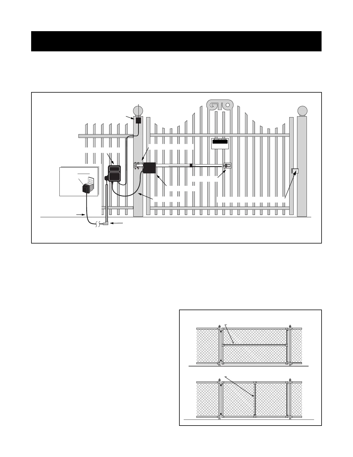
Single Gate /Pull-to-Open (Open-In)
The diagram below is an example of a single leaf, pull-to-open (open-in) installation on an ornamental iron gate. "Pull-to-
Open" is a gate which opens into the property. If you are installing a "Push-to-Open" (open-out) system (see page 31), or if
you are mounting the operator on a masonry column, please refer to page 36 before proceeding.
Installation of First (single) Gate Operator
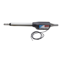
Horizontal Cross Member
Vertical Cross Member