33
Maintenance & Troubleshooting Guide
Maintenance:
• On all gates weighing 250 lbs. or more, routinely grease the ball bearing hinges at least 4 times a year; more
frequently if the gates are near a coastal area.
• A few mothballs in the control box helps to keep out insects which can damage circuits.
• Spray the push-pull tube with silicone spray about 4 to 12 times a year.
• Test all the safety accessories once per month! If they are not working, contact the installer or GTO Inc.
Gate sensitivity adjustments regulate the amount of force the operator needs to move the gate. If the hinges are in good
working condition, try using the S2 (“ Somewhat sensitive”) setting. In an area with high winds, it may need to be
set to a less sensitive.
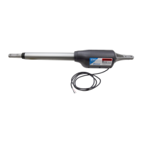
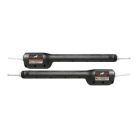
The operator has a 12 volt D.C. motor with mechanical limit switches.
To test the motor, put a volt meter on D.C. and place the meter leads on the wire connections inside the plastic cover above
the switches. The reading should be at least 11.5 volts when the system is active. If it is not, see the following
section “ The control board”.
To test the switches, put the meter on “ohms”. Place the leads on each of the wires on the switch. You should have an open
circuit. Click the switch and you should have .2 ohm’s. Do this for both switches.
To test the cable, put the meter on ohms. At one end of the cable place the lead on the green wire, and on the other end of the
cable place the lead on the green wire and the other wires. This should show a maximum of 1.0 ohms on the green
wire and nothing on the other wires. Test each wire as you have above. If all have the proper readings, then this is
not the problem.
Note: Inspect the cable for any signs of any punctures. Wires inside the PVC jacket can be shorted and the cable will still
show proper ohms.
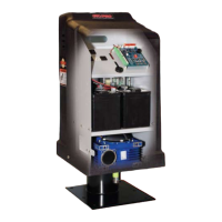
The control board: This is a micro processor board. The power that runs the gate comes from the battery which is recharged
through the board, by a 14 volt 40 va. (2.9 amp.) transformer.
There are 2 lights on the control board. These are for a quick reference only. All readings must be measured by a
volt meter!
The red light serves two purposes. The first is to aid in the programming (see page 20 “Programming the System”).
The second is to show the condition of the battery. If it is flashing, see the following section on “ Testing the
battery”. The normal state of this light is on but dim.
If the red light is flashing it means that the system has reached low voltage lockout, which means that the unit does
not have enough voltage to operate the system. One of the following problems may exist:
• Incorrect wire or trying to run the wrong gauge wire too far for the number of cycles that you need. See
chart on page 17
• Wires from the transformer or solar panel to the control board are broken or spliced.
• A transformer or solar panel that has no output voltage.
• Incorrect number of solar panels, or solar panels hooked up improperly.
The green light serves as a quick visual indication that the control board is receiving power from the transformer.