29
Step D3:Step D3:
Step D3:Step D3:
Step D3:
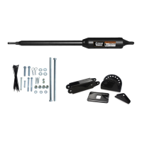
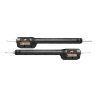
Turn back to page 9 on Installing the First (Single) Gate Operator and repeat Step 1 through 15
to install the second operator. This time in Step 15, however, the closed position stop plate on
the first gate will contact the leading edge of the second gate.
Step D4:Step D4:
Step D4:Step D4:
Step D4:
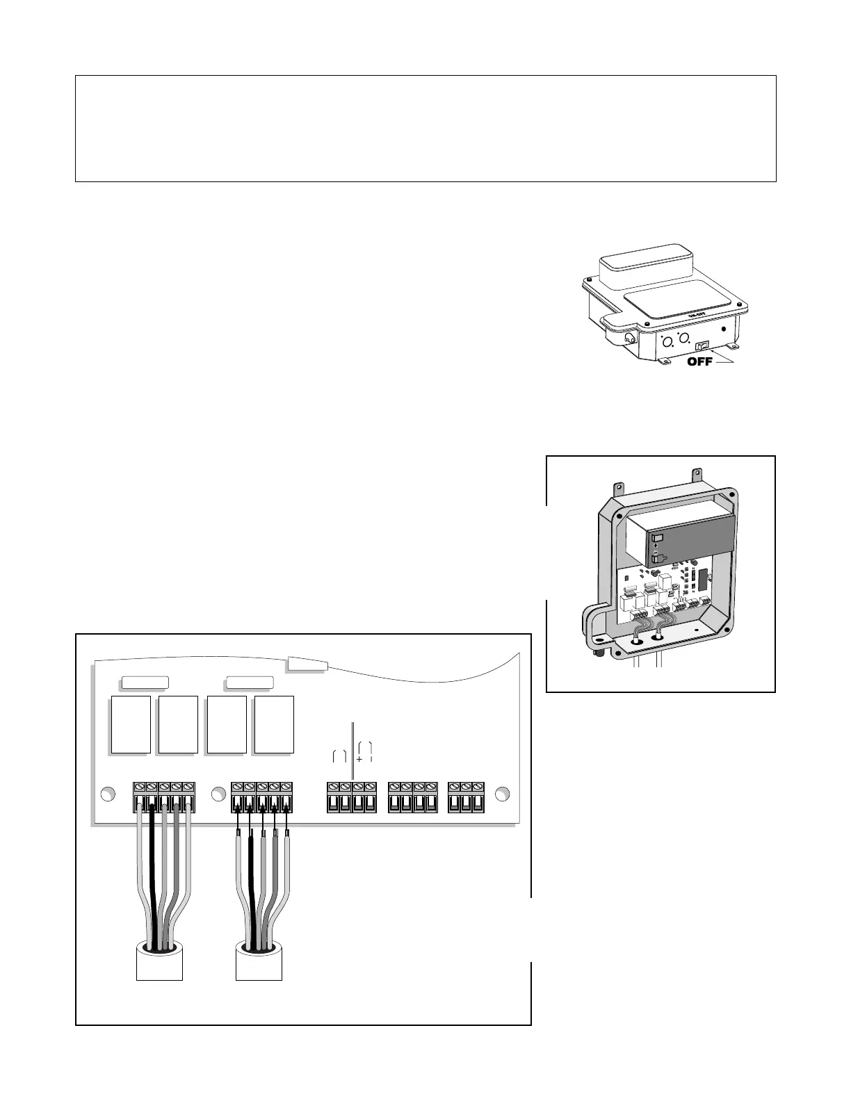
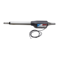
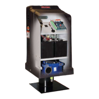
Turn power switch OFF and remove the control box cover. Using a screwdriver or
knife blade, remove the thin plastic knockout in the second operator connector hole
at the bottom of the control box. Work from the inside out to prevent any possible
damage to the control board.
Step D5:Step D5:
Step D5:Step D5:
Step D5:
Cut slot into driveway and run the power cable from the second operator to the control box by placing the power
cable in the PVC conduit. Seal the driveway with proper patch.
After the Second Operator is Installed on the Gate …
15 15
RED
BLK
GRN
ORG
BLU
RED
BLK
GRN
WHT
BLU
ORG
GRN
RED
BLK
GRN
ORG
BLU
RED
BLK
RED
BLK
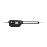
FIRST OPERATOR SECOND OPERATOR POWER IN ACCESSORY GTO RECEIVER
15 amp 15 amp
PRO 2000 Board
Terminal Blocks
TRANSFORMER
SOLAR
RED
BLACK
GREEN
ORANGE
BLUE
RED
BLACK
GREEN
ORANGE
BLUE
Power Cable
from First Operator
RED
BLACK
GREEN
ORANGE
BLUE
RED
BLACK
GREEN
ORANGE
BLUE
Power Cable
from Second Operator
Step D7:Step D7:
Step D7:Step D7:
Step D7:
Attach the wires to the second operator terminal block on the control
board as shown in the illustration. (See Step 19, on page 16.)
Step D6:Step D6:
Step D6:Step D6:
Step D6:
Attach the strain relief for the second operator power cable to the control
box. Then run the second operator power cable into the control box
through the strain relief.
NEVER splice wires together!