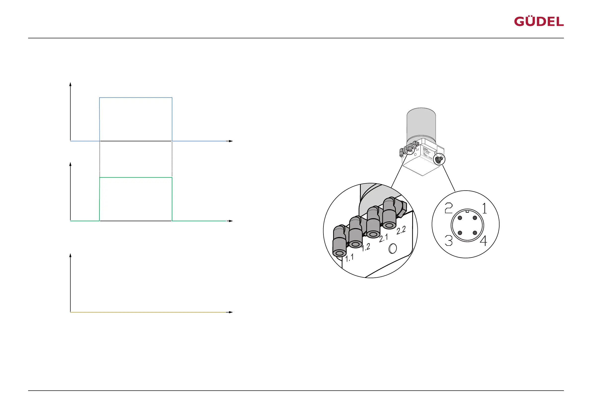
5.4.2 Connecting FlexxPump to power supply
Input signal PIN 1
Output signal PIN 4
U
U
+24 V
(High)
+ 0 V
(Low)
(Low)
+ 0 V
(High)
+24 V
t
t
Hydraulic output
t
V
Fig.5-7 Switching time diagram: Connecting FlexxPump to power supply
The FlexxPump is switched on as long as a constant voltage of 24 V DC is applied at PIN 1. Saved information is not lost when the FlexxPump is off. The output signal on PIN 4 is High (20...30V) dur-
ing normal operation. For regular lubricant dispensing, the FlexxPump must to be controlled by a PLC. A pulse rhythm needs to be sent for every lubrication cycle, by means of a control signal from
the PLC.
Commissioning
OPERATING MANUAL Automatic lubrication system
FlexxPump 404DLS
99079191943154059_v10.0_EN-US
45