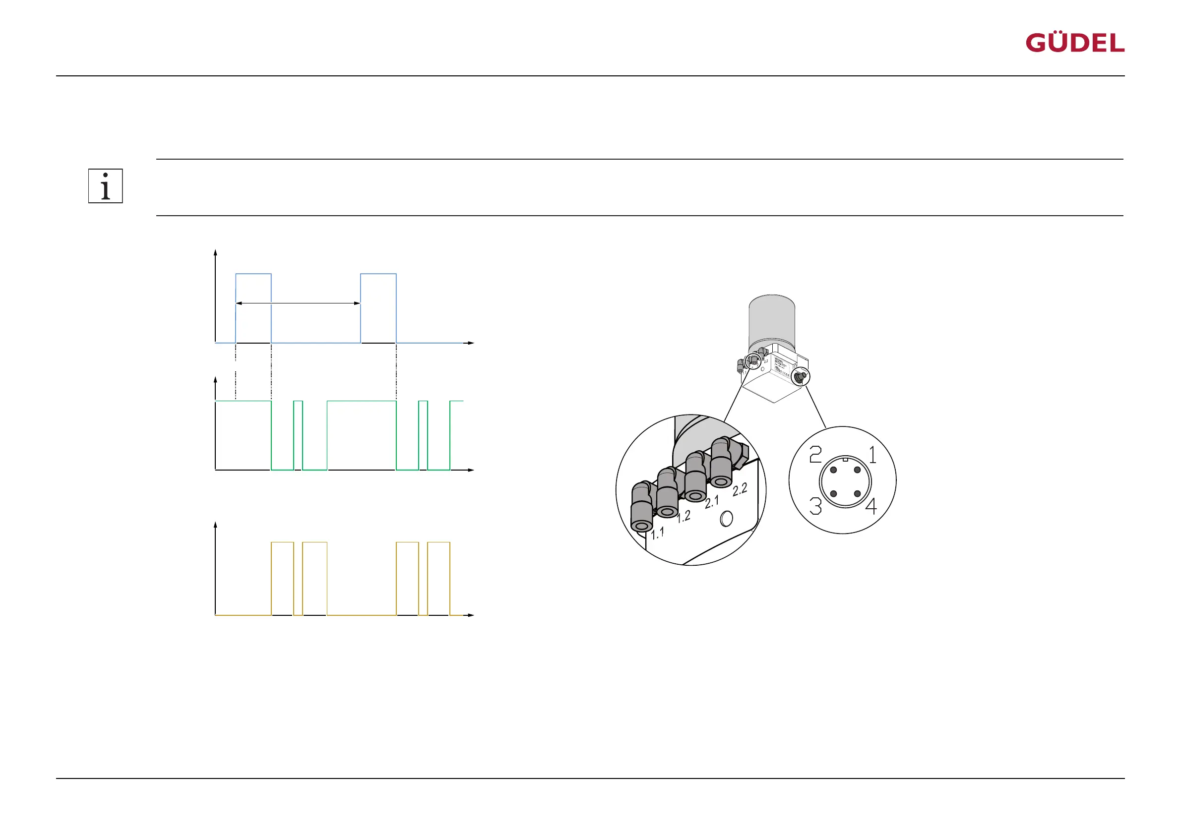
5.4.3 Lubrication
The following signal to PIN 2 results of 0.15 cm
3
of lubricant being dispensed to each of the four hydraulic outputs:
Accuracy of the impulses (High) on PIN 2: +/- 0.2s or +/- 10%!
Input signal PIN 2
Output signal PIN 4
U
U
+24 V
(High)
+ 0 V
(Low)
(Low)
+ 0 V
(High)
+24 V
t
t
8 s 8 s
3 s
2.3 s …
2.5 s
2.3 s …
2.5 s
9 s …
18 s
9 s …
18 s
9 s …
18 s
9 s …
18 s
1.1 or
1.2
2.1 or
2.2
Hydraulic output
2.1 or
2.2
1.1 or
1.2
min. 53 s
Pause
t
0.15 cm³
0.15 cm³
0.15 cm³
0.15 cm³
V
Fig.5-8 Switching time diagram: Normal case
At the displayed signal on PIN 2, each of the four hydraulic outputs dispense 0.15 cm
3
of lubricant. Start of the dispensing = output 1.1 or 1.2, then output 2.1 or 2.2. Each hydraulic output is filled with
lubricant by its respective piston. Each piston carries out a lubrication stroke. Per lubrication stroke, 0.15 cm
3
of lubricant is pumped into the respective hydraulic output. The output signal at PIN 4 is
High (+20...30V) during normal operation. During an actual motor run of the FlexxPump, the signal switches to Low (+0V). Normally this takes between approx. 9 and 18 seconds, depending on the
length of the hydraulic hoses and the viscosity of the lubricant. The signal then switches back to High (+24V).
Commissioning
OPERATING MANUAL Automatic lubrication system
FlexxPump 404DLS
99079191943154059_v10.0_EN-US
47