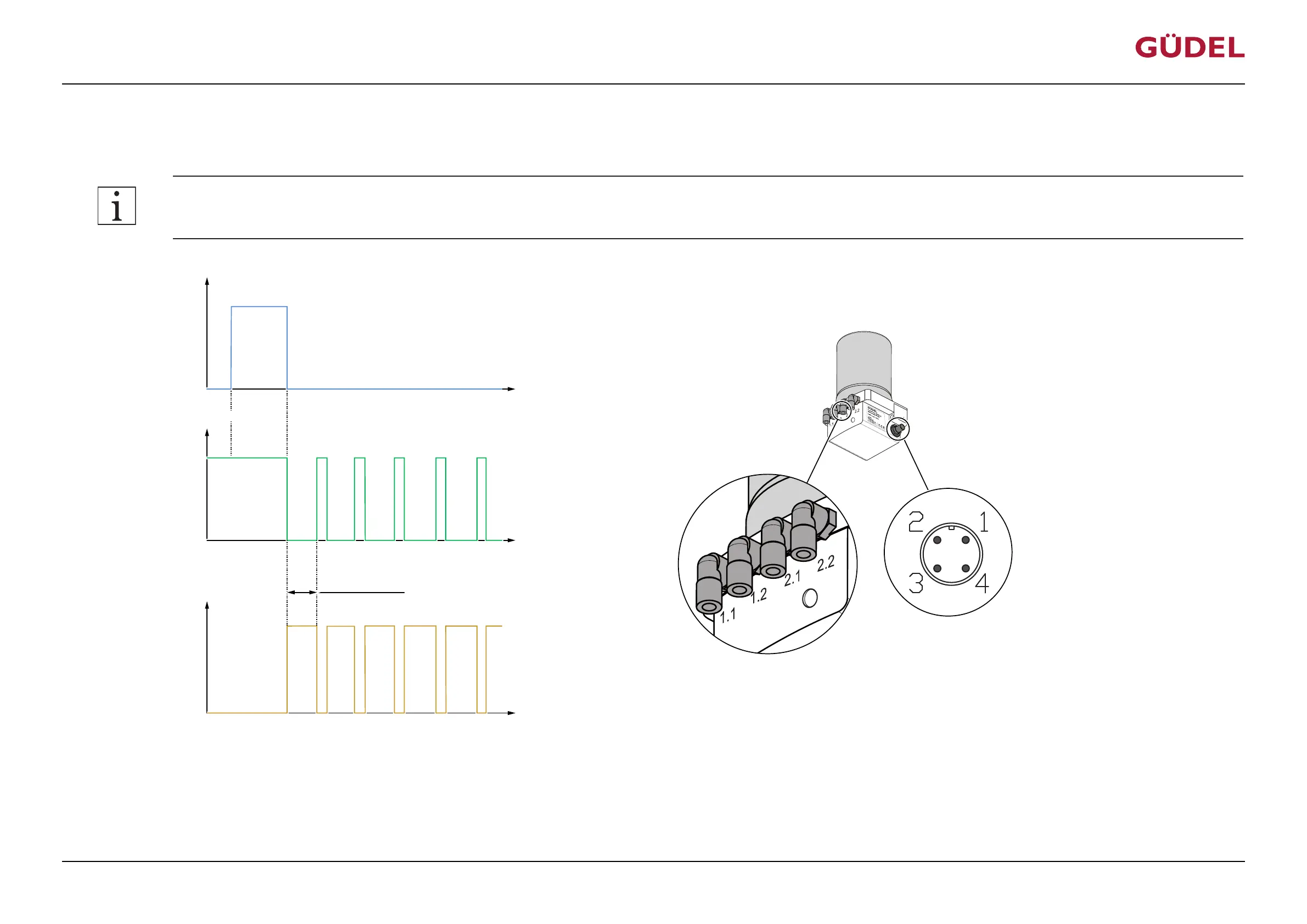
5.4.4 Filling hydraulic lines / venting the FlexxPump
The following signal on PIN 2 causes 20 x 0.15 cm
3
of lubricant to be dispensed at each of the four hydraulic outputs:
Accuracy of the impulses (High) on PIN 2: +/- 0.2s or +/- 10%!
Input signal PIN 2
Output signal PIN 4
U
U
+24 V
(High)
+ 0 V
(Low)
(Low)
+ 0 V
(High)
+24 V
t
t
12 s
3 s
2.3 s …
2.5 s
2.3 s …
2.5 s
9 s …
18 s
9 s …
18 s
9 s …
18 s
9 s …
18 s
1.1 or
1.2
2.1 or
2.2
Hydraulic output
2.1 or
2.2
1.1 or
1.2
t
0.15 cm³
0.15 cm³
0.15 cm³
0.15 cm³
V
2.3 s …
2.5 s
2.3 s …
2.5 s
2.3 s …
2.5 s
9 s …
18 s
0.15 cm³
1.1 or
1.2
Repetition 80x
…
…
Fig.5-9 Switching time diagram: Filling hydraulic lines / venting the FlexxPump
The filling process starts with the displayed signal on PIN 2. The filling process takes a maximum of 1600 seconds. The filling process is continued after the FlexxPump is switched on if it was inter-
rupted by switching off the FlexxPump. The output signal at PIN 4 is High (+20...30V) during normal operation. During an actual motor run of the FlexxPump, the signal switches to Low (+0V). Nor-
mally this takes between approx. 9 and 18 seconds, depending on the length of the hydraulic hoses and the viscosity of the lubricant. The signal then switches back to High (+24V).
Commissioning
OPERATING MANUAL Automatic lubrication system
FlexxPump 404DLS
99079191943154059_v10.0_EN-US
49