20
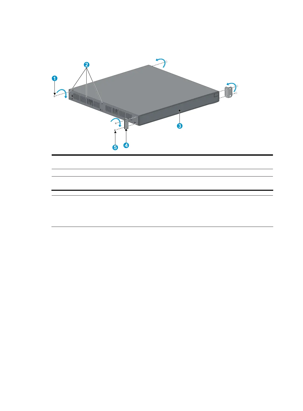
Step4 Unpack the load-bearing screws (packed with the rear mounting brackets), and install them to the
appropriate positions on the two sides of the switch, as shown in Figure 26.
Figure 26 Rack mounting by using front and rear mounting brackets
(1) Load-bearing screw (2) Load-bearing screw positions (select one as
needed)
(3) Switch front panel (4) Front mounting bracket
(5) Screw (packaged with the front mounting bracket)
for fixing the front mounting bracket to the switch
NOTE:
The switch provides three positions on both sides to mount a load-bearin
screw. Select a proper position
according to the actual requirements. The rear mounting brackets support the switch by the load-bearin
screws.
Step5 Determine where to install the switch to the rack, and install the cage nuts to the corresponding positions
on the front and rear rack posts.
Step6 Fix the rear mounting brackets to the rear rack posts by using the M6 screws, as shown in Figure 27.

 Loading...


