37
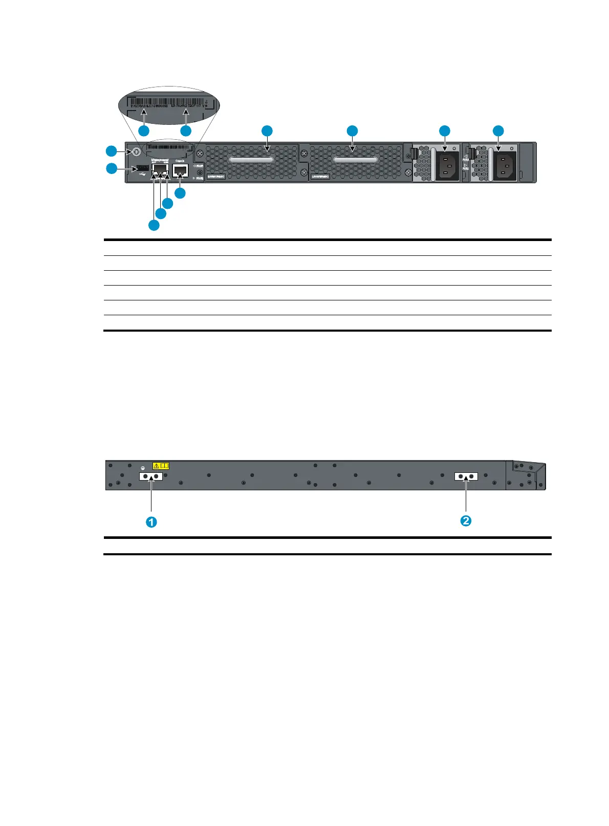
Figure 42 Rear panel (LS-5820V2-52QF-H5)
(1) USB port (2) Grounding screw (auxiliary grounding point 2)
(3) Barcode (4) Product code
(5) Fan tray slot 1 (6) Fan tray slot 2
(7) Power module slot 1 (8) Power module slot 2
(9) Console port (10) LINK LED for the management Ethernet port
(11) Management Ethernet port (12) ACT LED for the management Ethernet port
The S5820V2-52QF switch comes with the power module slots empty and the filler modules for the
slots as accessories. You can install one or two power modules for the switch as needed. In Figure
40 an
d Figure 41, two
LSVM1AC300 power modules are installed. For more information about
installing and removing a power module, see "Installing/removing a power module."
The S582
0V2-52QF switch also comes with the fan tray slots empty. You must install two fan trays of
the same model for the switch. In Figure 40 and Figure 41, two LSWM1F
ANSC fan trays are installed.
For more information about installing and removing a fan tray, see "Installing/removing a fan tray."
Figure 43
Left side panel
(1) Primary grounding point (2) Auxiliary grounding point 1
9
10
5 6 7 8
11
12
3 4
1
2
 Loading...


