52
{ If the device connects to one distribution frame, connect port 1 on the device to port 1 on the
distribution frame, port 2 on the device to port 3 on the distribution frame, and port 3 on the
device to port 5 on the distribution frame.
{ If the device connects to two distribution frames, connect port 1 on the device to port 1 on
distribution frame 1, port 2 on the device to port 1 on distribution frame 2, and port 3 on the
device to port 2 on distribution frame 1.
LEDs
System status LED
The system status LED shows the operating status of the switch.
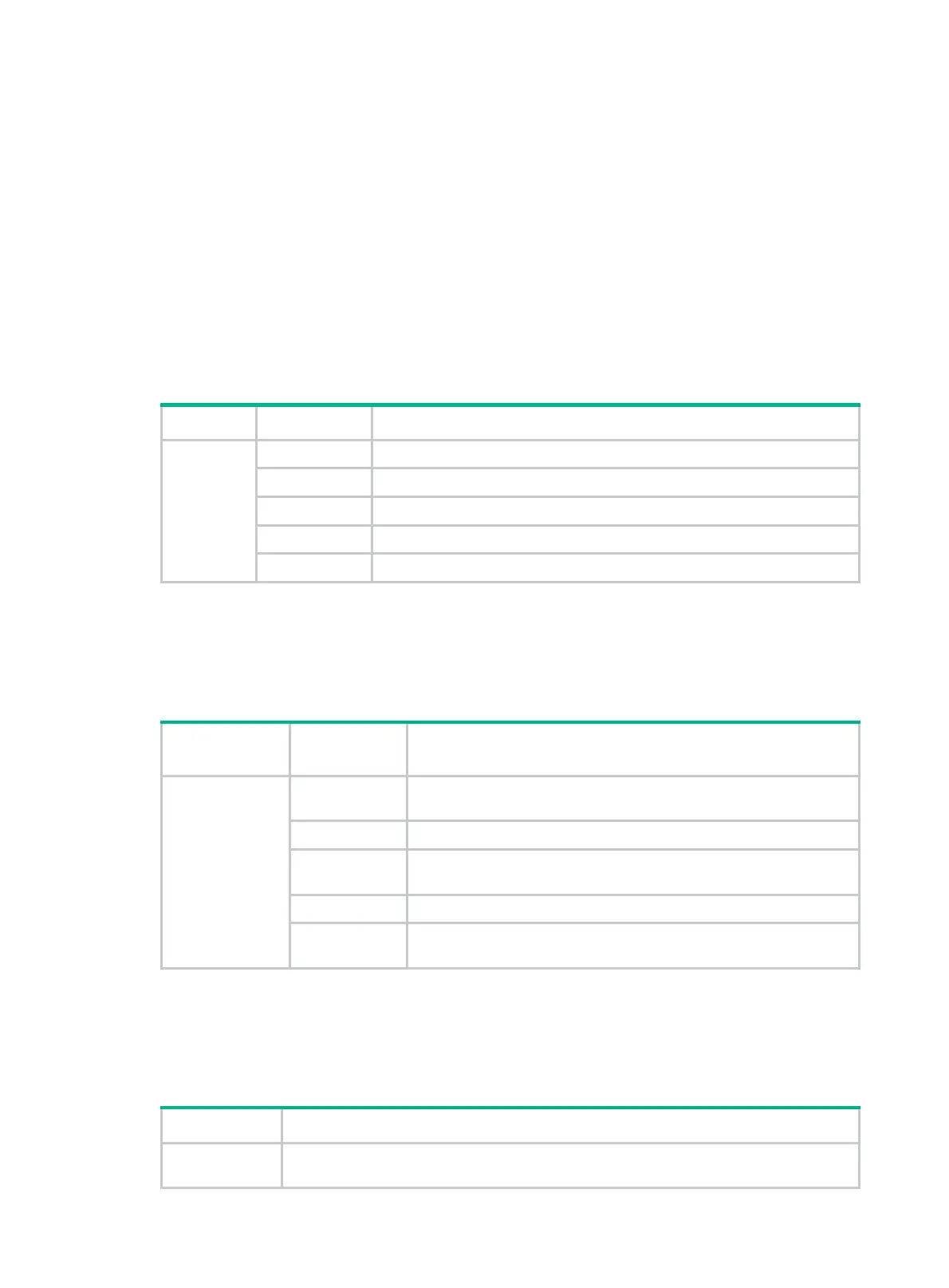
Table 21 System status LED description
LED mark Status Description
SYS
Steady green The switch is operating correctly.
Flashing green The switch is performing power-on self test (POST).
Steady red The system has failed to pass POST or has problems such as fan failure.
Flashing red Some ports have failed to pass POST.
Off The switch is powered off or has failed to start up.
SFP+ port LED
Each SFP+ port has a status LED to show port operating status and activities.
Table 22 SFP+ port LED description
Transmission
technology
LED status Description
Ethernet
Steady green
A transceiver module or cable has been correctly installed. The port
has a link and is operating at 10 Gbps.
Flashing green The port is sending or receiving data at 10 Gbps.
Steady yellow
A transceiver module or cable has been correctly installed. The port
has a link and is operating at 1 Gbps.
Flashing yellow The port is sending or receiving data at 1 Gbps.
Off
No transceiver module or cable has been installed or no link is
present on the port.
QSFP+ port LED
Each QSFP+ port has a status LED to show port operating status and activities.
Table 23 QSFP+ port LED description
LED status Description
Steady green
A transceiver module or cable has been correctly installed. The port has a link and is
operating at 40 Gbps.
 Loading...


