27
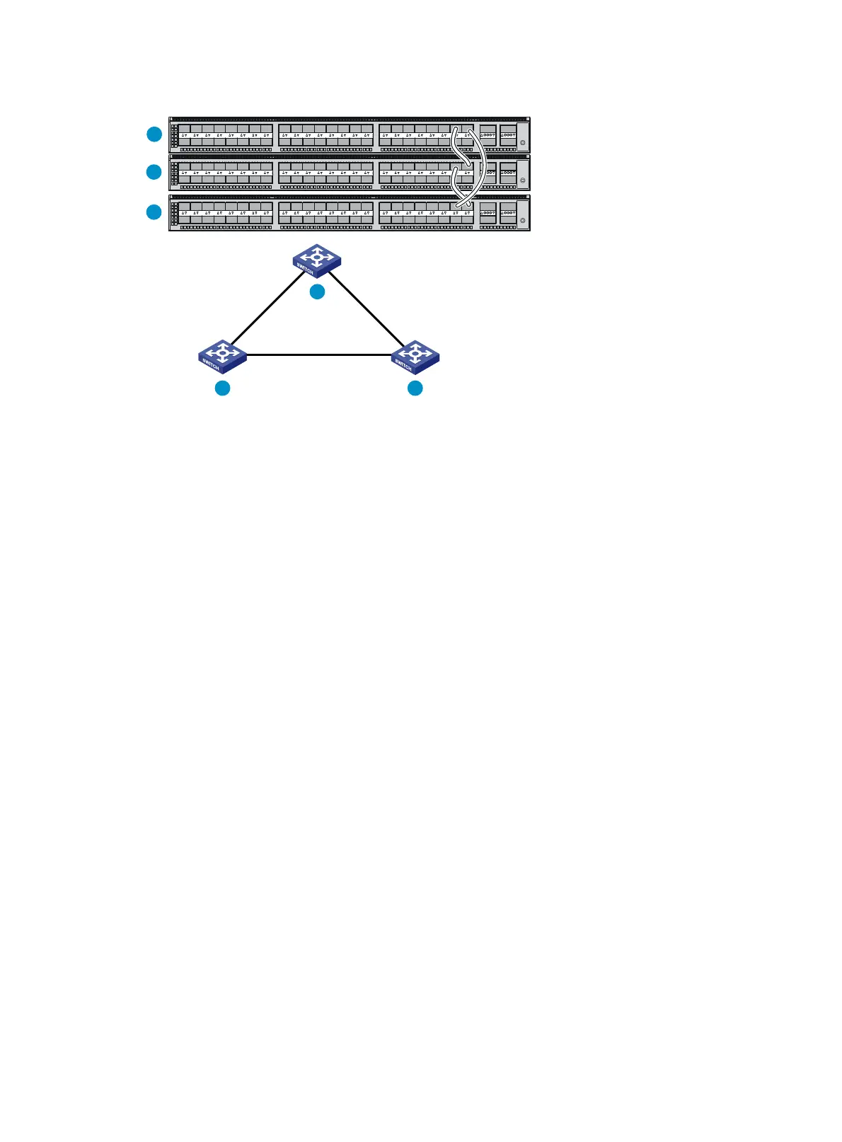
Figure 29 IRF fabric in ring topology
Identifying physical IRF ports on the member switches
Identify the SFP+ or QSFP+ ports to be used for IRF connections on the member switches according
to your topology and connection scheme.
All the SFP+ and QSFP+ ports on the S5820V2-52QF, S5820V2-52QF-U, and S5820V2-54QS-GE
switches, all the 1/10-GE Ethernet ports and QSFP+ ports on the S5820V2-52Q switch, and all the
SFP+ ports on the S5830V2-24S switch can be used for IRF connections.
Follow these guidelines when you identify 1/10-GE Ethernet ports and SFP+ ports to be used for IRF
connections:
• On an S5820V2-52QF, S5820V2-52QF-U, S5830V2-24S, or S5820V2-48S switch, the SFP+
ports are grouped by port number in ascending order, starting from one. Every four SFP+ ports
form one group.
• On an S5820V2-54QS-GE switch, SFP+ ports numbered 49, 50, 51, and 52 form one group.
• On an S5820V2-52Q switch, the 1/10-GE Ethernet ports are grouped by port number in
ascending order, starting from one. Every four 1/10-GE Ethernet ports form one group.
• A 1/10-GE Ethernet port/SFP+ port can be bound to an IRF port or operate as a service port.
When a 1/10-GE Ethernet ports/SFP+ port is bound to an IRF port, other 1/10-GE Ethernet
ports/SFP+ ports in the same port group cannot be used as service ports, and vice versa.
A common practice is to use one 1/10-GE Ethernet port/SFP+ port group for IRF connections, and
bind every two 1/10-GE Ethernet ports/SFP+ ports in the group to an IRF port for increased
bandwidth and availability.
Planning the cabling scheme
For the S5830V2-24S/S5820V2-48S/S5820V2-52QF/S5820V2-52QF-U/S5820V2-54QS-GE
switches, use SFP+/QSFP+ DAC cables or SFP+/QSFP+ transceiver modules and fibers to connect
the IRF member switches. For the S5820V2-52Q switches, use twisted pair cables, QSFP+ DAC
cables, or QSFP+ transceiver modules and fibers to connect the IRF member switches. If the IRF
member switches are far away from one another, choose the SFP+/QSFP+ transceiver modules with
optical fibers. If the IRF member switches are all in one equipment room, choose twisted
pair/SFP+/QSFP+ DAC cables. For more information about available SFP+/QSFP+ DAC cables and
transceiver modules, see "SFP+ port" a
nd "QSFP+ port."
IRF-port1
IRF-port2
IRF-port1
IRF-port1
IRF-port2
IRF-port2
1
2
3
1
2 3
 Loading...


