28
The following subsections describe several H3C recommended IRF connection schemes, and all
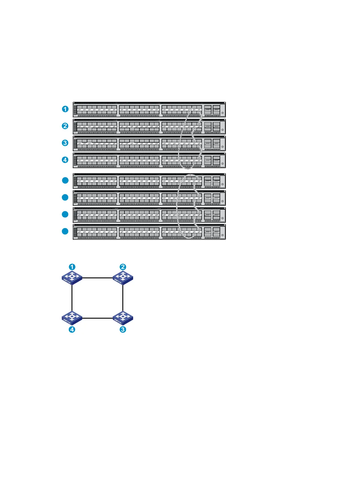
these schemes use a ring topology.
Connecting the IRF member switches in one rack
Use short-haul and long-haul SFP+ DAC cables to connect the IRF member switches (four switches
in this example) in a rack as shown in Figure 30. The
switches in the ring topology (see Figure 31)
are in the same order as connected in the rack.
Figure 30 Connecting the switches in one rack
Figure 31 IRF fabric topology
Connecting the IRF member switches in a ToR solution
You can install IRF member switches in different racks side by side to deploy a top of rack (ToR)
solution.
Figure 32 sh
ows an example for connecting four top of rack IRF member switches by using
SFP+/QSFP+ DAC cables, and SFP+/QSFP+ transceiver modules, and optical fibers. The topology
is the same as Figure 31.
1
2
3
4
 Loading...


