34
The S5830V2-24S switch comes with the power module slots empty and the filler modules for the
slots as accessories. You can install one or two power modules for the switch as needed. In Figure
34, two LSV
M1AC650 power modules are installed. For more information about installing and
removing a power module, see "Installing/removing a power module."
The S583
0V2-24S switch also comes with the fan tray slots empty. You must install two fan trays of
the same model for the switch. In Figure 34, two LS
VM1FANSC fan trays are installed. For more
information about installing and removing a fan tray, see "Installing/removing a fan tray."
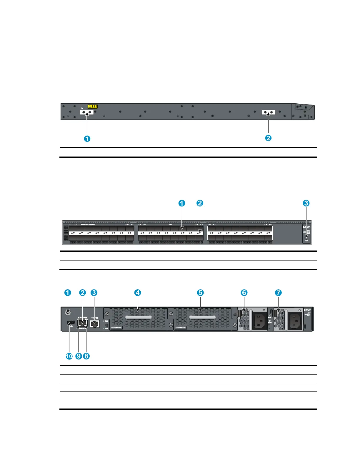
Figure 35
Left side panel
(1) Primary grounding point (2) Auxiliary grounding point 1
S5820V2-48S
Figure 36 Front panel
(1) SFP+ port (2) SFP+ port LED
(3) System status LED (SYS)
Figure 37 Rear panel
(1) Grounding screw (auxiliary grounding point 2) (2) Management Ethernet port
(3) Console port (4) Fan tray slot 1
(5) Fan tray slot 2 (6) Power module slot 1
(7) Power module slot 2 (8) LINK LED for the management Ethernet port
(9) ACT LED for the management Ethernet port (10) USB port
 Loading...


