54
Appendix D Cooling system
The cooling system of the switch uses front-back ventilation. To guarantee that this cooling system
can effectively work, you must consider the site ventilation design when you plan the installation site
for the switches.
Table 27 Switch fan tray ventilation description
Switch model Fan tray Air flow direction
• S5820V2-48S
• S5820V2-52QF
• S5820V2-52QF-U
• S5820V2-54QS-GE
LSWM1FANSC
Air flows in through the power module side and exhausts
at the network port side
LSWM1FANSCB
Air flows in through the network port side and exhausts at
the power module side
S5820V2-52Q
LSWM1HFANSC
Air flows in through the power module side and exhausts
at the network port side
LSWM1HFANSCB
Air flows in through the network port side and exhausts at
the power module side
S5830V2-24S
LSVM1FANSC
Air flows in through the power module side and exhausts
at the network port side
LSVM1FANSCB
Air flows in through the network port side and exhausts at
the power module side
NOTE:
To ensure correct ventilation, fan trays on the switch must have the same air flow direction.
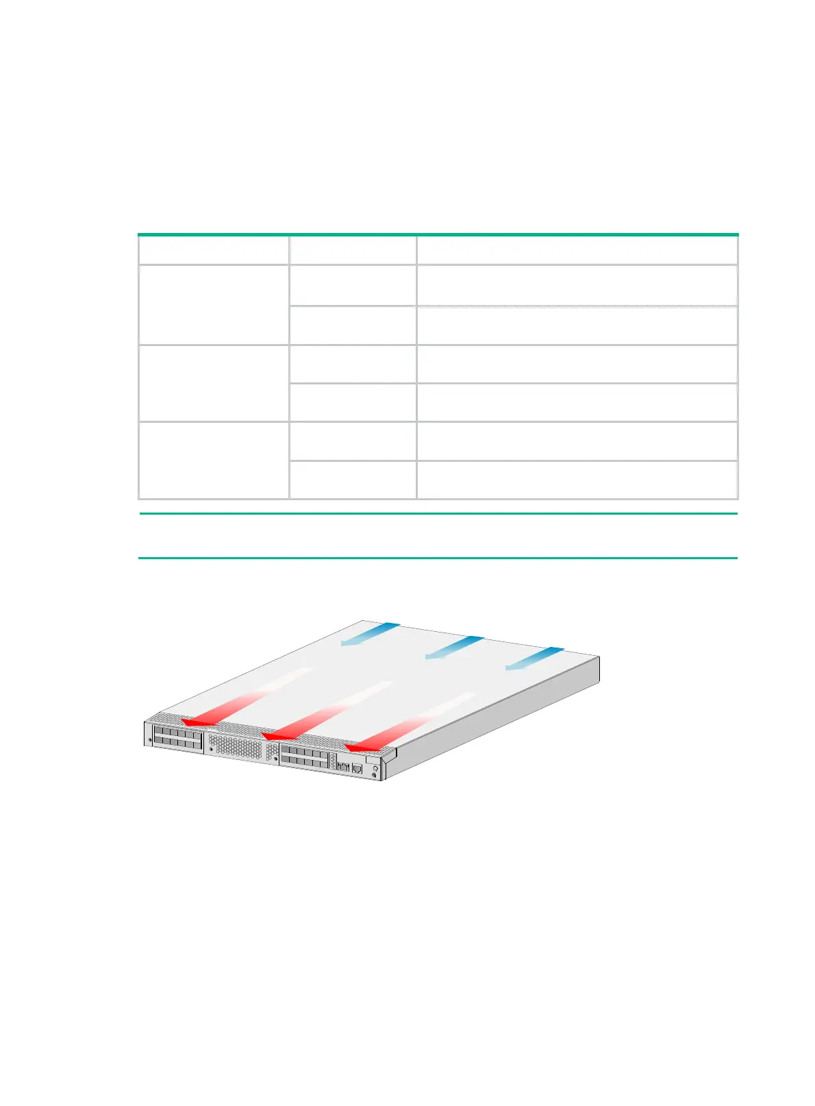
Figure 56 Power module side to network port side air flow direction (S5830V2-24S chassis
with LSVM1FANSC fan trays)
 Loading...


