HI 1756-WS WEIGH SCALE MODULE
3-4
Installing the Module I/
O Connector
About the Module
I/O Connector
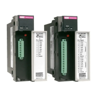
The I/O Connector at the front of the module connects
the module to the Remote Terminal Assembly (-
RTA), a load sensor, or the HI 215IT Series Junction
Box, depending on how many load sensors are
installed in the weighing system. See below for the
pin-out diagram, which is also located on the inside of
the module door. (See Fig. 3-4 & 3-5)
Step 1. Open the Module door to gain access to
the I/O connector. (See Fig. 3-4 & 3-5)
Step 2. Install the cable and connector so it allows
the module door to be shut.
Step 3. With the plug oriented correctly (See the
pin-out diagram above), plug the I/O male
connector into the I/O connector at the
front of the module.
Step 4. Verify that the connector is completely
plugged in before operating the module.
NOTE: Most problems are due to loose connections. Be sure
to check the I/O connection first if you have a problem
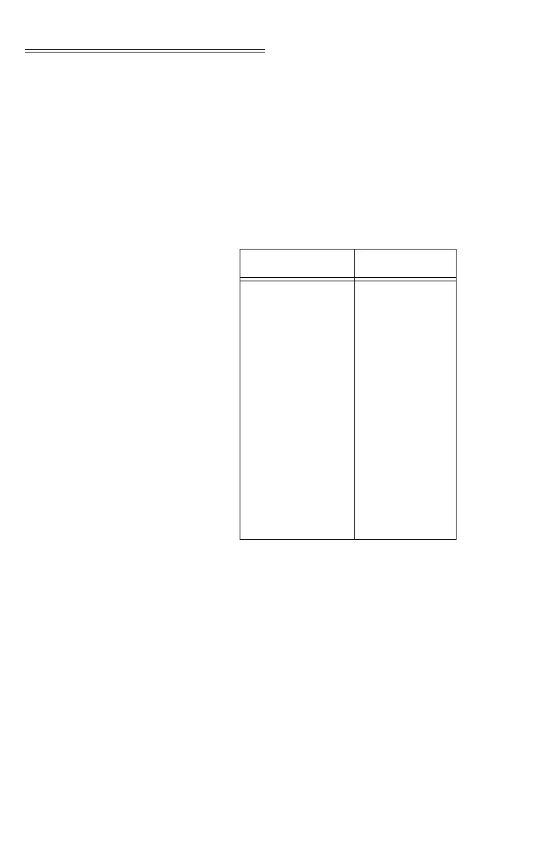
Single Channel Dual Channel
Pin 1 Exc+
Pin 2 Sense+
Pin 3 Sig+
Pin 4 Sig-
Pin 5 Sense-
Pin 6 Exc-
Pin 7 C2+
Pin 8 C2-
Pin 9 Shield
Pin 1 Exc+
Pin 2 Sense+
Pin 3 Sig+
Pin 4 Sig-
Pin 5 Sense-
Pin 6 Exc-
Pin 7 C2+
Pin 8 C2-
Pin 9 Shield
Pin 10 Exc+
Pin 11 Sense+
Pin 12 Sig+
Pin 13 Sig-
Pin 14 Sense-
Pin 15 Exc-
Pin 16 C2+
Pin 17 C2-
Pin 18 Shield