CHAPTER 7 - Troubleshooting
7-3
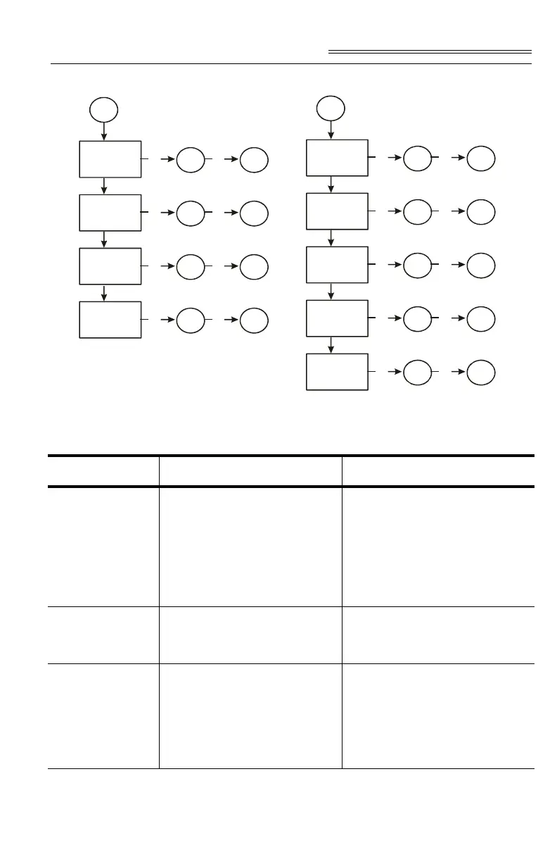
FIG. 7-2 COMMAND DEFINITIONS AND ACTIONS
Name / Code # Definition Action
erroradconvert 1 B1: Load cell input out of range
(i.e., voltage not 0-15 mV and
flashing red LED will display).
Can result from overloaded or
mismounted load cell.In this
state weight readings do not
repond to changes.
C1: Check the voltage levels to
the module from each load cell. +5
V for excitation and sense lines
and 0 - 15 mV on signal lines. If
voltage is bad, to find a problem
load cell, disconnect each one at
the summing box.
erroradfailure 2 B2: Output from the A/D con-
verter to processor is bad. The
module shows a solid red LED.
C2: Contact Customer Support to
return module for repair.
statusinmotion 64 B3: The rate of scale weight
change over 1 second exceeds
the motion tolerance setting. If
the setting is too low, motion
may be indicated when no
changes are occurring.
C3: If the weight is actually
changing, stabilize it. If not,
increase the motion tolerance set
-
ting until the motion bit goes off
with static weight.
Status = 1
A1
Yes
C1
Yes
B1
Status = 2
Yes
C2
Yes
B2
Status = 64
Yes
C3
Yes
B3
Status = 256
Yes
C4
Yes
B4
Status = -3
A2