4C20 Gasoline Engine Repair Manual
clearance measurement
Plastic probe for
104
(b) Check the crankshaft radial clearance:
9. Crankshaft
and main journals of the crankshaft;
(1) Remove the main bearing caps, clean them
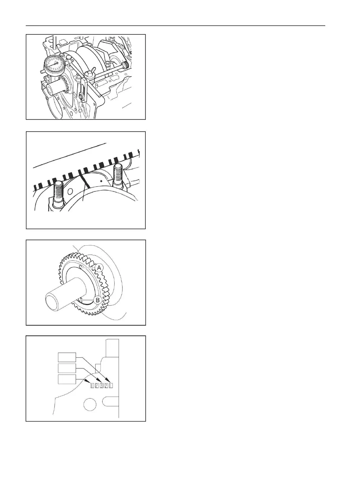
(a) Measure the axial free play of the crankshaft:
(2) Place a plastic feeler gauge of the correct width on the crankshaft
journals.
10. Check the position of the alignment mark of the sprocket
ÿ Standard values: 0.022 - 0.044 mm
go shaft;
(1) Fix the dial gauge with bracket to the cylinder block with a bolt so
that the dial gauge foot touches the crank web;
balance shaft drive
No. 1
(a) The angle relative to the alignment mark (A) of the sprocket and the
alignment groove of the crankshaft (B) must be 180±0.2°.
(2) Press the crankshaft against the indicator and install
(3) The plastic feeler gauge should be placed perpendicular to the axis
of the crankshaft at the top of the main journal;
(4) Install the main bearing caps and tighten them (tightening torque:
40±2 N•m), but do not rotate the crankshaft;
it at zero;
11. Selection of liners of main bearings
(a) The bore group number for the shells of each main bearing is stamped on
the cylinder block;
(3) Move the crankshaft away from the indicator and check the indicator
reading.
(5) Remove the main bearing caps;
ÿ Standard values: 0.110 - 0.310 mm
(6) Measure the width of the plastic gap gauge and compare it with the
reference scale.
No. 5
No. 3
Machine Translated by Google


 To Next Page