Home
HAVAL
Engine
4S20
Page 58 (Section III. Sump, Oil Receiver and Oil Pump)
HAVAL 4S20 - Section III. Sump, Oil Receiver and Oil Pump
194 pages
Manual
Save Page as PDF
To Next Page
To Next Page
To Previous Page
To Previous Page
Loading...
Chapter
IX.
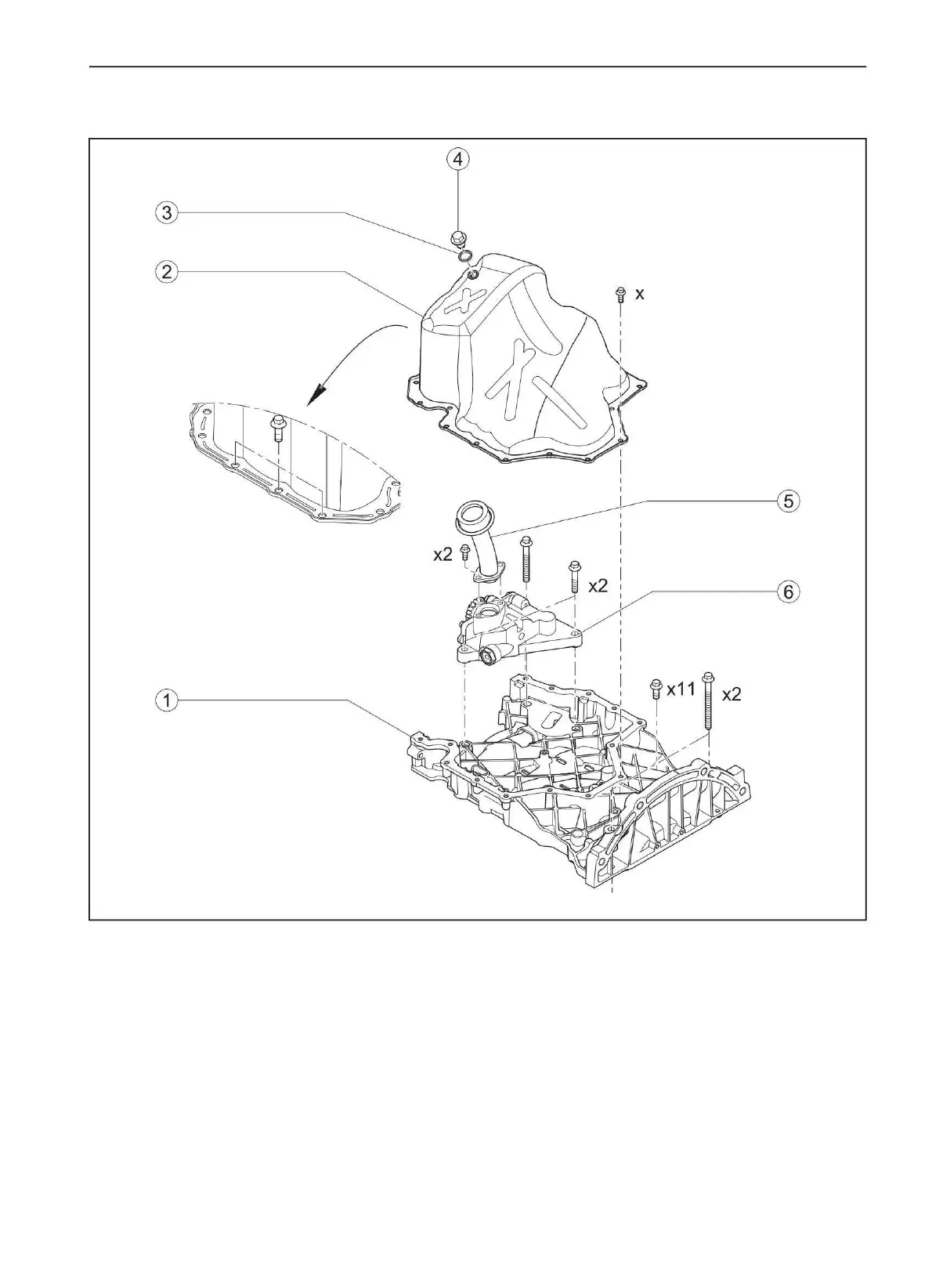
Lubrication
system
4
-
Drain
plug
5
-
Oil
receiver
6
-
Oil
pump
1
-
Upper
part
of
the
oil
pan
2
-
Lower
part
of
the
oil
pan
3
-
Combined
drain
plug
gasket
Section
III.
Sump,
oil
receiver
and
oil
pump
18
51
Machine Translated by Google
57
59
Table of Contents
Main Page
Table of Contents
7
Chapter I. Introduction
9
Section I. Terms of Use of this Manual
9
Markings
11
Chapter II. Technical Information about the Engine
12
Section I Main Specifications
12
Section II Tightening Torques for Threaded Connections
13
Chapter III. Inspection Intervals and Service Intervals
13
Chapter IV. Engine Attachment
14
Section I. Engine Attachment Layout
15
Section II. V-Ribbed Belt
15
Section III. Generator
16
Section IV. Air Conditioning Compressor
17
Section V Idler Pulley and Engine Attachment Drive Belt Tensioner
18
Section VI. Power Steering Pump
19
Section VII. Starter
20
Section VIII. Bracket for Fastening the Front Support and Branch Pipe of the Forced Crankcase Ventilation System
21
Chapter V. Turbocharging System
22
Section I. Layout of the Turbocharging System
22
Section II. Turbocharger
24
Chapter VI. Inlet and Outlet Systems
30
Section I. Intake System
30
Section II. Exhaust System
34
Chapter VII. Supply System
38
Section I. Power System Layout
38
Section II. Supply System
39
Chapter VIII. Cooling System
44
Section I. Coolant
44
Section II. Coolant Pump
45
Section III. Thermostat
50
Section IV. Hot Coolant Outlet Pipe
52
Chapter IX. Lubrication System
54
Section I. Oil Line
54
Section II. Engine Oil
55
Section III. Sump, Oil Receiver and Oil Pump
58
Section IV. Oil Cooler and Oil Filter
63
Chapter X. Cylinder Head
68
Section I. Cylinder Head Cover
68
Section II. Cylinder Head
72
Section III. Valve Mechanism
78
Section IV. Timing Chain
86
Section V. Oil Pump Drive Chain and Drive Chain Balancer Shafts
90
Chapter XI. Cylinder Block
94
Section I. Piston Connecting Rod
94
Section II. Rear Crankshaft Oil Seal
101
Section III. Timing Mechanism Cover (GRM)
104
Crankshaft
108
Section V. Balance Shaft
115
Chapter XII. Engine Management System
118
Section I. Installing the System Sensors
118
Section II. General Information about the System
120
Section III. Basic Control Algorithms
123
Components of the Electronic Control Unit
130
Diagnosis System Car
150
Section VI. Daily and Periodic Maintenance
177
Section VII. Repair Tools
178
Section VIII. Troubleshooting for Common Troubleshooting
179
Section IX. Typical Data Received from the Delphi Electronic Fuel Injection System
189
Section X. Self-Adaptation of the European-Standard On-Board Self-Diagnosis (EOBD) System in the Event of a Malfunction of the Crankshaft Position Sensor
192