Chapter XII. Engine management system
windings
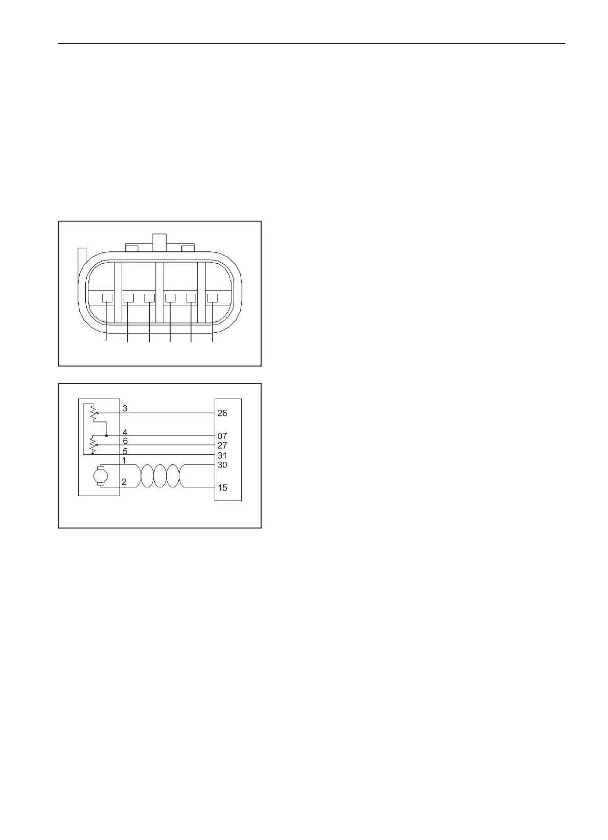
1 2 3 4 5 6
139
3. Pin arrangement
ÿ 1. "Positive" contact of the electric motor;
(b) Avoid damage to contacts and excessive frequent
(a) Four pins of the throttle position sensor are gold-plated, two pins of the
electric motor are plated
1. Appointment
ÿ 2. "Negative" contact of the electric motor;
ÿ 5. Throttle position sensor input
elephants;
ÿ 3. TPS2 output;
(a) Throttle valve control requires a throttle position sensor to detect throttle
position and condition. The voltage signal from the non-contact throttle
position sensor is sent to the engine control unit, which processes the
throttle position data in real time, taking into account operating
parameters.
at 5 V;
power on and off;
ÿ 6. TPS1 output.
2. Features:
ÿ 4. "Ground" of the throttle position sensor
(c) Do not damage the label during installation;
(d) Do not connect to non-system power;
tin.
(a) TPS1: TPS 1 output;
4. Troubleshooting
(e) Do not drop the throttle body (from any height);
(a) See "Electronic Throttle" on page 137.
(b) TPS2: TPS 2 output.
(e) Do not remove the protective cover of the throttle body
damper until installation is complete.
5. Installation notes
(a) To avoid damage to the throttle body and its electrical interface during
installation, use the following guidelines:
e/
motor
Throttle position sensor
E/Motor-
E/Motor+
Machine Translated by Google
 Loading...