USE ONLY GENUINE REPLACEMENT PARTS
Page 8 of 20 Control Station Rev. A
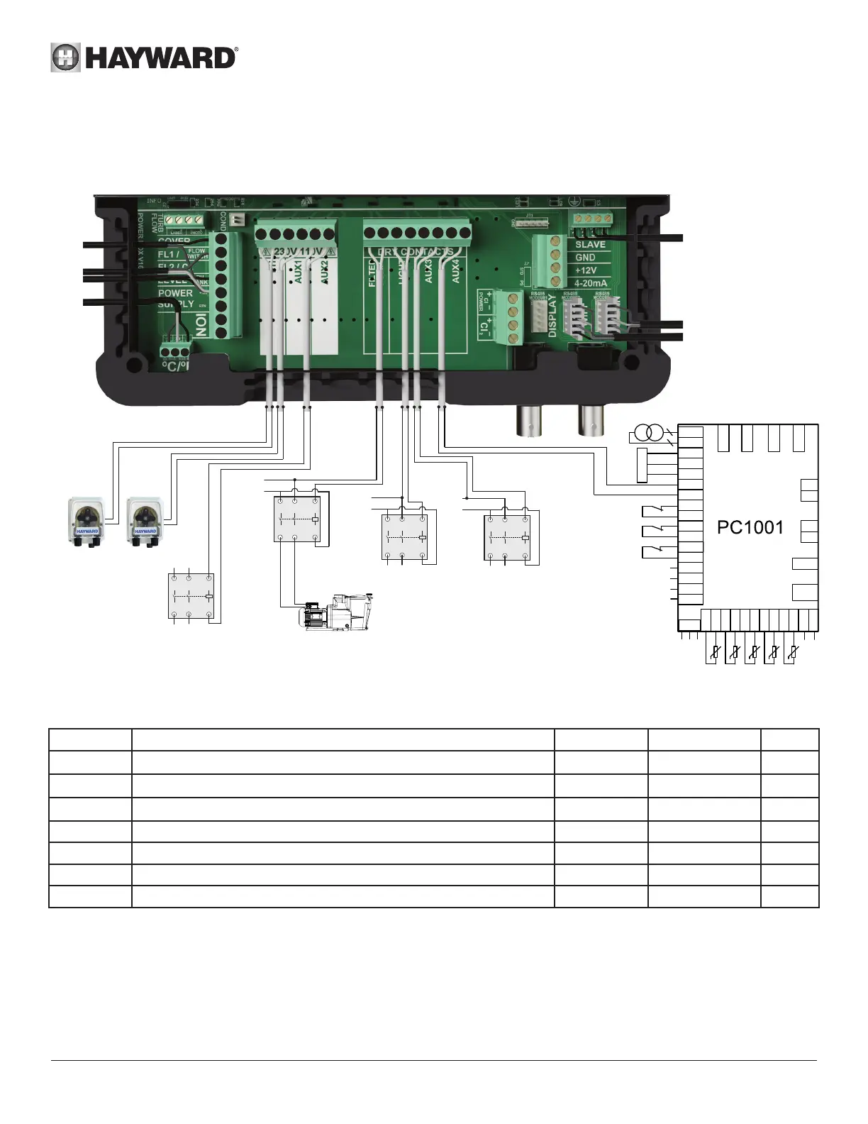
Electrical installation and wiring
Connect the Control Station to a permanent power outlet.
This circuit must be protected by a residual current device (RCD) (residual current: 30 mA max.).
Cover
FL1
pHredoX
1
2 3 4 5 6
7 9
10 13 1411 12
8
A
B
C
D
E
F
G
H
Level
I J K
LIGHT
1
2
3
4
A1
A2
L
N
pH Cl
AUX 3
1
2
3
4
A1
A2
L
N
AUX 2
1
2
3
4
A1
A2
N L
FILTER PUMP
1
2
3
4
A1
A2
L
N
AUX 4
EnergyLine / Easy Temp / EcoPac / PowerLine
FS
HP
LP
TC
12V
Controller
BLU
Y/G
BRN
FS
FS
LP
LP
HP
HP
2 2
t
5K
t
5K
t
5K
t
5K
IT
IT
OT
OT
AT
AT
CT
CT
OUT3
OUT4
OUT5
AC-N
3
4
3
4
CN19
GND
AI05
GND
AI04
GND
AI03
GND
AI02
GND
CN1
CN2
12V
NET
GND
DI01
GND
DI02
GND
DI03
GND
DI04
GND
DI05
GND
AI01
GND
DI06
GND
CN6
AI06
CN16
GND
+5V
t
5K
SUT
SUT
OUT1 OUT2
Description of outgoing relays
Name Description Terminals Type of output Imax
pH
Peristaltic acid pump 230 V
1 - 2 Voltage output 1 A
Cl
Peristaltic chlorine pump 230 V
3 - 4 Voltage output 1 A
Aux2
Auxiliary voltage output 230 V
5 - 6 Voltage output 1 A
Filter Pump Filtration pump control 7 - 8 Dry contact
Light Lighting control 9 - 10 Dry contact
Aux3 Auxiliary dry contact 11 - 12 Dry contact
Aux4 Auxiliary dry contact (or heating control). 13 - 14 Dry contact
If no heating system is installed on Aux4, it can be used as another auxiliary contact. To do this, contact Hayward technical
support.
Remote screen
option
Wi module
Variable speed
pump
Temperature
Probe