USE ONLY GENUINE REPLACEMENT PARTS
Page 9 of 20 Control Station Rev. A
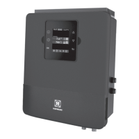
Connecting a heating system (Aux 4)
The Control Station is compatible with all types of pool heaters such as heat pumps, electric heaters or even heat exchangers.
Connecting to a Hayward heating system fitted with a remote On/Off control
Connect a 2 x 0.75 mm² electric cable (not supplied) across terminals (13)-(14) of auxiliary contact Aux 4, then connect it across
the DI01 and GND terminals on electronic circuit board PC1001/PC1002 of the Hayward heat pump or any other compatible
equipment (see the installation instructions). Set the set point of the heat pump or heating system to maximum. The Control Station
will use its own water temperature probe to control the heating set point.
Compatible equipment includes the seasonal Energyline Pro, the inverter Energyline Pro, the All Seasons Energyline Pro,
EasyTemp, EcoPac, PowerLine and other brands with a remote On/Off control.
Connecting to a Hayward heating system not fitted with a remote On/Off control
In this case, the heating is controlled in series with the flow controller. Connect a 2 x 0.75 mm² cable in series with the flow control
system.
Set the heating system set point to maximum. The Control Station will use its own water temperature probe to control the heating
set point.
Connecting inputs:
Name Description Terminals Type of input
FL1 Flow switch B - E Dry contact
Cover Not used A - E Dry contact
Level Acid container level detection D - E Dry contact
ION Not used G - H
-
°C / F°
Black wire K
-
Yellow wire J
-
Red wire I
-
Characteristics
Power supply
230 V
50 Hz
Current consumption 100 mA
Power consumption 23 W
Safety rating IPX4
Characteristics of pH and ORP relays Imax (pH+Cl+Aux2) = 3,15A , Pmax (PH+Cl+Aux2) = 725 W
Dimensions 270 x 220 x 150
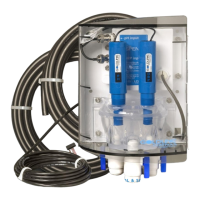
Connecting the ORP option (Optional)
Insert the ORP probe into the measuring chamber.
Connect the BNC connector on the ORP probe to the redox BNC input on the Control Station.