USE ONLY GENUINE REPLACEMENT PARTS
Page 10 of 20 Control Station Rev. A
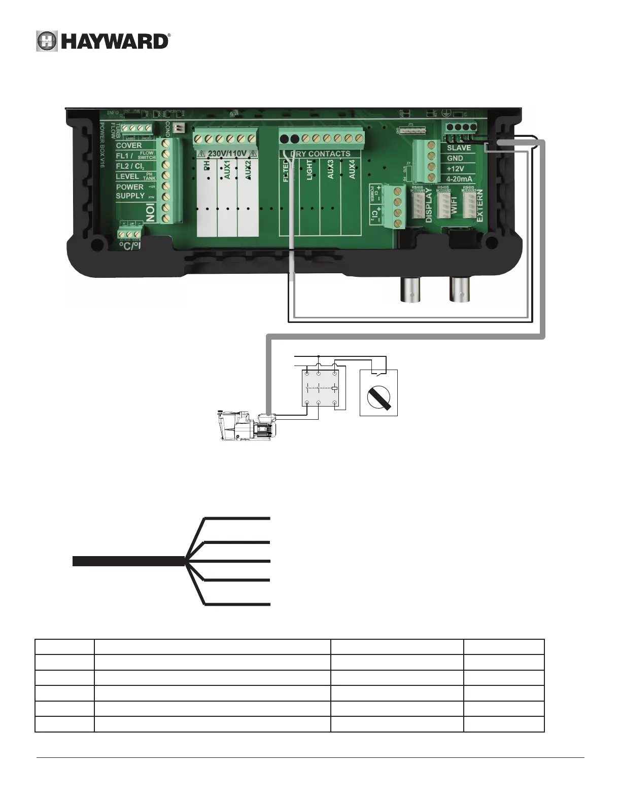
Connecting a Hayward variable-speed pump with digital inputs
pHredoX
7 8
1
2 3 C
FILTER PUMP
1
2
3
4
A1
A2
L
N
OFF
AUTO
When using a Hayward variable-speed pump fitted with digital inputs, bridge the common black wire, connected to terminal (C),
to terminal (7) and follow the connection instructions given in the following table.
You will have to strip the digital cable back 15 cm and cut the orange wire.
Brown wire (BRN) = V1 = 1500 rpm by default
Green wire (G) = V2 = 2400 rpm by default
White wire (WHT) = V3 = 3000 rpm by default
Red wire (R) = DI4 = On/Off
Black wire (BLK) = C = Common
Name Description Terminals Colour
V1 Low pump speed (V1) 1 Brown (BRN)
V2 Average pump speed (V2) 2 Green (G)
V3 High pump speed (V3) 3 White (WHT)
C Common C - 7 Black (BLK)
DI4 On/Off 8 Red (R)