23
PME-MP60/MP07
A0616-13.4 en HBM
Measurement signal for rotation speed, 0° , F1 (+)
Ground
Transducer
shaft
n
Cable shielding
BK
RD
GY
Measurement signal for rotation speed, 90° , F2 (+)
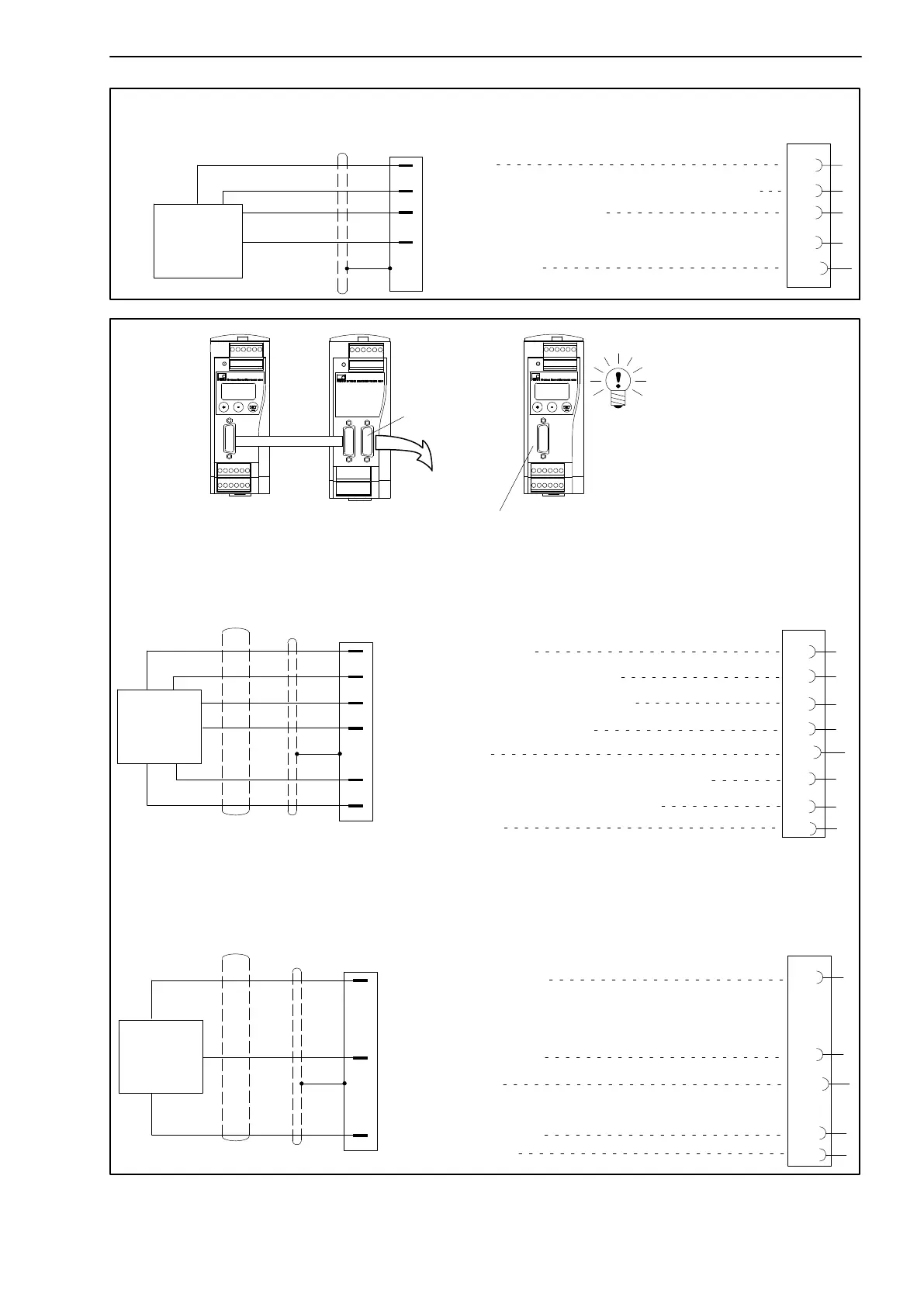
Rotation speed measurement, angle of rotation measurement;
(torque transducer T4WAS3)
4
12
15
11
Hsng.
YE
GN
Supply voltage +5 V (TTL)
Connection for MP60...
Connection B
Torque measurement (asymmetric signals)
(torque transducer T30FNA..T34FN, T10F-KF1)
Supply voltage for preamplifier (-15 V)
Supply voltage for preamplifier (+15 V)
Square-wave excitation voltage for rotor 54 V/81 V
Square-wave excitation voltage for rotor 0 V
Cable shielding
Zero operating voltage
Measurement signal for torque,
12 V (5 - 30 V) peak, 5 - 15 kHz
WH
BK
RD
BU
GN
GY
YE
8
5
15
6
Hsng.
13
Zero operating voltage
Cable shielding
WH
RD
GY
Measurement signal for rotation speed, F2 (+), 25 V
(5 - 30 V) peak-to-peak (90° out-of-phase for detection
of direction of rotation)
Measurement signal for rotation speed, F1 (+), 25 V
(5 - 30 V) peak-to-peak
Rotation speed measurement, angle of rotation measurement
(asymmetric signals)
(torque transducer T30FNA..T34FN)
8
15
Hsng.
Transducer
shaft
Md
Transducer
shaft
n
GN
YE
PK
WH
BN
GY
T34FN only
12
WH
BK
BU
MP60 MP07 MP60
Torque
Rotation speed
Transducer shaft
Connection A
Connection B
Connection A
Connection B
T34FN only
NOTE
For use with MP07:
Set the DIP switches in
the MP60 to
asymmetrical (see page
13).
Transducer error
7
Transducer error
12
7
Fig. 4.5: Connection for MP60 and MP07