4
PME-MP60/MP07
A0616-13.4 enHBM
Frequency, pulse counter, incremental transducer
(symmetric signals)
Frequency, pulse counter, incremental transducer
(asymmetric signals)
Ground
Cable shielding
Hsng.
Zero index (+)
Zero index (-)
Transducer error
f1, 0
o
f2, 90
o
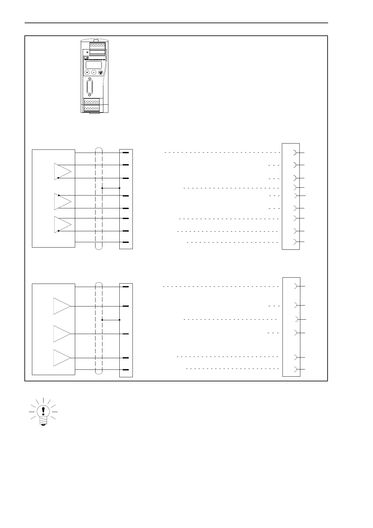
Measurement signal for rotation speed, F1 (+), 0°
Ground
8
12
f1, 0
o
f2, 90
o
Ground
Cable shielding
8
12
Hsng.
Zero index (+)
Transducer error
f1, 0
o
f2, 90
o
MP60
13
14
15
2
3
7
Connection A
Connection A
Connection A
Measurement signal for rotation speed, F1 (-), 0°
Measurement signal for rotation speed, F2 (-), 90°
Measurement signal for rotation speed, F2 (+), 90°
Measurement signal for rotation speed, F1 (+), 0°
Measurement signal for rotation speed, F2 (+), 90°
15
2
7
Fig. 4.6: Connection for MP60
NOTE
The MP60(DP) can indicate the transducer errors generated by the tor-
que sensor. But to do this, the error signal from the torque sensor must
be connected across Pin 7 of the transducer plugs (15−pin sub−D plugs)
on the MP60(DP).
The ”transducer error” function in the MP60(DP) must also be activated.